Threads Part ||
Applying boosts
Back in KiExitDispatcher, you saw that KiProcessThreadWaitList is called to process any threads in the deferred ready list. It is here that the boost information passed by the caller is processed. This is done by looping through each DeferredReady thread, unlinking its wait blocks (only Active and Bypassed blocks are unlinked), and setting two key values in the kernel’s thread control block: Adjust-Reason and AdjustIncrement. The reason is one of the two Adjust possibilities seen earlier, and the increment corresponds to the boost value. KiDeferredReadyThread is then called. This makes the thread ready for execution by running two algorithms: the quantum and priority selection algorithm (which you are about to see in two parts) and the processor selection algorithm (which is shown in the “Processor selection” section later in this chapter).
Let’s first look at when the algorithm applies boosts, which happens only in cases when a thread is not in the real-time priority range. For an AdjustUnwait boost, it will be applied only if the thread is not already experiencing an unusual boost and only if the thread has not disabled boosting by calling SetThreadPriorityBoost, which sets the DisableBoost flag in the KTHREAD. Another situation that can disable boosting in this case is if the kernel has realized that the thread has actually exhausted its quantum (but the clock interrupt did not fire to consume it) and it has come out of a wait that lasted less than two clock ticks.
If these situations are not currently true, the new priority of the thread will be computed by adding the AdjustIncrement to the thread’s current base priority. Additionally, if the thread is known to be part of a foreground process (meaning that the memory priority is set to MEMORY_PRIORITY_FOREGROUND, which is configured by Win32k.sys when focus changes), this is where the priority-separation boost (PsPrioritySeparation) is applied by adding its value on top of the new priority. This is also known as the foreground priority boost, which was explained earlier.
Finally, the kernel checks whether this newly computed priority is higher than the current priority of the thread, and it limits this value to an upper bound of 15 to avoid crossing into the real-time range. It then sets this value as the thread’s new current priority. If any foreground separation boost was applied, it sets this value in the ForegroundBoost field of the KTHREAD, which results in a PriorityDecrement equal to the separation boost.
For AdjustBoost boosts, the kernel checks whether the thread’s current priority is lower than the AdjustIncrement (recall this is the priority of the setting thread) and whether the thread’s current priority is below 13. If so, and priority boosts have not been disabled for the thread, the AdjustIncrement priority is used as the new current priority, limited to a maximum of 13. Meanwhile, the UnusualBoost field of the KTHREAD contains the boost value, which results in a PriorityDecrement equal to the lock- ownership boost.
In all cases where a PriorityDecrement is present, the quantum of the thread is also recomputed to be the equivalent of only one clock tick, based on the value of KiLockQuantumTarget. This ensures that foreground and unusual boosts will be lost after one clock tick instead of the usual two (or other configured value), as will be shown in the next section. This also happens when an AdjustBoost is requested but the thread is running at priority 13 or 14 or with boosts disabled.
After this work is complete, AdjustReason is now set to AdjustNone.
Removing boosts
Removing boosts is done in KiDeferredReadyThread as boosts and quantum recomputations are being applied (as shown in the previous section). The algorithm first begins by checking the type of adjustment being done.
For an AdjustNone scenario, which means the thread became ready perhaps due to a preemption, the thread’s quantum will be recomputed if it already hit its target but the clock interrupt has not yet noticed, as long as the thread was running at a dynamic priority level. Additionally, the thread’s priority will be recomputed. For an AdjustUnwait or AdjustBoost scenario on a non-real-time thread, the kernel checks whether the thread silently exhausted its quantum (as in the prior section). If so, or if the thread was running with a base priority of 14 or higher, or if no PriorityDecrement is present and the thread has completed a wait that lasted longer than two clock ticks, the quantum of the thread is recomputed, as is its priority.
Priority recomputation happens on non-real-time threads. It’s done by taking the thread’s current priority, subtracting its foreground boost, subtracting its unusual boost (the combination of these last two items is the PriorityDecrement), and finally subtracting 1. This new priority is bounded with the base priority as the lowest bound and any existing priority decrement is zeroed out (clearing unusual and foreground boosts). This means that in the case of a lock-ownership boost or any of the other unusual boosts explained, the entire boost value is now lost. On the other hand, for a regular AdjustUnwait boost, the priority naturally trickles down by 1 due to the subtraction by 1. This lowering eventually stops when the base priority is hit due to the lower bound check.
There is another instance where boosts must be removed, which goes through the KiRemoveBoostThread function. This is a special-case boost removal that occurs due to the lock-ownership boost rule, which specifies that the setting thread must lose its boost when donating its current priority to the waking thread (to avoid a lock convoy). It is also used to undo the boost due to targeted deferred procedure calls (DPCs) as well as the boost against ERESOURCE lock-starvation boost. The only special detail about this routine is that when computing the new priority, it takes special care to separate the ForegroundBoost and UnusualBoost components of the PriorityDecrement to maintain any GUI foreground-separation boost that the thread accumulated. This behavior, which appeared starting with Windows 7, ensures that threads relying on the lock-ownership boost do not behave erratically when running in the foreground, or vice-versa.
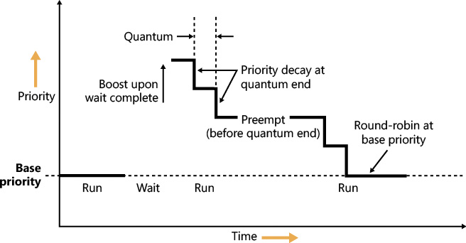
Figure 4-12 displays an example of how normal boosts are removed from a thread as it experiences quantum end.
Priority boosts for multimedia applications and games
Although Windows’ CPU-starvation priority boosts might be enough to get a thread out of an abnormally long wait state or potential deadlock, they simply cannot deal with the resource requirements imposed by a CPU-intensive application such as Windows Media Player or a 3D computer game.
Skipping and other audio glitches have long been a common source of irritation among Windows users. The Windows user-mode audio stack exacerbates this situation because it offers even more chances for preemption. To address this, client versions of Windows use the MMCSS driver (described earlier in this chapter), implemented in %SystemRoot%\System32\Drivers\MMCSS.sys. Its purpose is to ensure glitch-free multimedia playback for applications that register with it.
![]() Note
Note
Windows 7 implements MMCSS as a service (rather than a driver). This posed a potential risk, however. If the MMCSS managing thread blocked for any reason, the threads managed by it would retain their real-time priorities, potentially causing system-wide starvation. The solution was to move the code to the kernel where the managing thread (and other resources used by MMCSS) could not be touched. There are other benefits to being a kernel driver, such as holding a direct pointer to process and thread objects rather than IDs or handles. This bypasses searches based on IDs or handles and allows faster communication with the scheduler and Power Manager.
Client applications can register with MMCSS by calling AvSetMmThreadCharacteristics with a task name that must match one of the subkeys under HKLM\SOFTWARE\Microsoft\Windows NT\CurrentVersion\Multimedia\SystemProfile\Tasks. (The list can be modified by OEMs to include other specific tasks as appropriate.) Out of the box, the following tasks exist:
![]() Audio
Audio
![]() Capture
Capture
![]() Distribution
Distribution
![]() Games
Games
![]() Low Latency
Low Latency
![]() Playback
Playback
![]() Pro Audio
Pro Audio
![]() Window Manager
Window Manager
Each of these tasks includes information about the various properties that differentiate them. The most important one for scheduling is called the Scheduling Category, which is the primary factor determining the priority of threads registered with MMCSS. Table 4-4 shows the various scheduling categories.
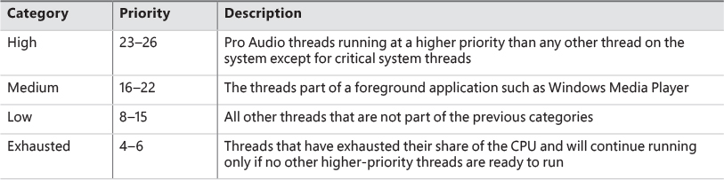
The main mechanism behind MMCSS boosts the priority of threads inside a registered process to the priority level matching their scheduling category and relative priority within this category for a guaranteed period. It then lowers those threads to the exhausted category so that other, non-multimedia threads on the system can also get a chance to execute.
By default, multimedia threads get 80 percent of the CPU time available, while other threads receive 20 percent. (Based on a sample of 10 ms, that would be 8 ms and 2 ms, respectively.) You can change this percentage by modifying the SystemResponsiveness registry value under the HKLM\SOFTWARE\Microsoft\Windows NT\CurrentVersion\Multimedia\SystemProfile key. The value can range from 10 to 100 percent (20 is the default; setting a value lower than 10 evaluates to 10), which indicates the CPU percentage guaranteed to the system (not the registered audio apps). MMCSS scheduling thread runs at priority 27 because they need to preempt any Pro Audio threads to lower their priority to the exhausted category.
As discussed, changing the relative thread priorities within a process does not usually make sense, and no tool allows this because only developers understand the importance of the various threads in their programs. On the other hand, because applications must manually register with MMCSS and provide it with information about what kind of thread this is, MMCSS does have the necessary data to change these relative thread priorities—and developers are well aware that this will happen.
EXPERIMENT: MMCSS priority boosting
1. Run Windows Media Player (wmplayer.exe). (Other playback programs might not take advantage of the API calls required to register with MMCSS.)
2. Play some audio content.
3. Using Task Manager or Process Explorer, set the affinity of the Wmplayer.exe process so that it runs on only one CPU.
4. Start the Performance Monitor tool.
5. Using Task Manager, change Performance Monitor’s priority class to Realtime so it will have a better chance of recording activity.
6. Click the Add Counter toolbar button or press Ctrl+I to open the Add Counters dialog box.
7. Select the Thread object and then select the Priority Current.
8. In the Instances box, type Wmplayer, click Search, and then select all its threads.
9. Click the Add button and click OK.
10. Open the Action menu and choose Properties.
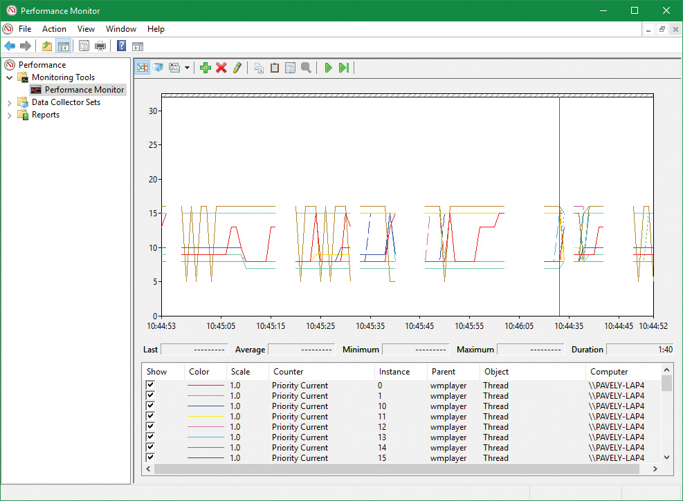
11. On the Graph tab, change the maximum vertical scale to 32. You should see one or more priority-16 threads inside Wmplayer, which will be constantly running unless there is a higher-priority thread requiring the CPU after they are dropped to the exhausted category.
12. Run CPU Stress.
13. Set the activity level of thread 1 to Maximum.
14. The priority of thread 1 is Normal. Change it to Time Critical.
15. Change the CPUSTRES priority class to High.
16. Change the CPUSTRES affinity to use the same CPU used for Wmplayer. The system should slow down considerably, but the music playback should continue. Every so often, you’ll be able to get back some responsiveness from the rest of the system.
17. In Performance Monitor, notice that the WmPlayer priority 16 threads drop from time to time as shown here:
MMCSS’ functionality does not stop at simple priority boosting, however. Because of the nature of network drivers on Windows and the NDIS stack, DPCs are quite common mechanisms for delaying work after an interrupt has been received from the network card. Because DPCs run at an IRQL level higher than user-mode code (see Chapter 6 for more information on DPCs and IRQLs), long-running network card driver code can still interrupt media playback—for example, during network transfers or when playing a game.
MMCSS sends a special command to the network stack, telling it to throttle network packets during the duration of the media playback. This throttling is designed to maximize playback performance—at the cost of some small loss in network throughput (which would not be noticeable for network operations usually performed during playback, such as playing an online game). The exact mechanisms behind it do not belong to any area of the scheduler, so we’ll leave them out of this description.
MMCSS also supports a feature called deadline scheduling. The idea is that an audio-playing program does not always need the highest priority level in its category. If such a program uses buffering (obtaining audio data from disk or network) and then plays the buffer while building the next buffer, deadline scheduling allows a client thread to indicate a time when it must get the high priority level to avoid glitches, but live with a slightly lower priority (within its category) in the meantime. A thread can use the AvTaskIndexYield function to indicate the next time it must be allowed to run, specifying the time it needs to get the highest priority within its category. Until that time arrives, it gets the lowest priority within its category, potentially freeing more CPU time to the system.
Autoboost
Autoboost is a framework targeted at the priority-inversion problem described in the previous section. The idea is to track lock owners and lock waiters in such a way that would allow boosting the appropriate threads’ priorities (I/O priority as well if needed) to allow threads to make forward progress. The lock information is stored in a static array of KLOCK_ENTRY objects inside the KTHREAD structure. The current implementation uses a maximum of six entries. Each KLOCK_ENTRY maintains two binary trees: one for locks owned by the thread and the other for locks waited on by the thread. These trees are keyed by priority so that constant time is required to determine the highest priority to which boosting should be applied. If boost is required, the owner’s priority is set to the waiter’s priority. It may also boost I/O priority if these were issued with low priority. (See Chapter 6 for more on I/O priority.) As with all priority boosts, the maximum priority achievable by Autoboost is 15. (The priority of real-time threads is never boosted.)
Current implementation uses the Autoboost framework for pushlocks and guarded mutexes synchronization primitives, which are exposed to kernel code only. (See Chapter 8 in Part 2 for more on these objects.) The framework is also used by some executive components for specialized cases. Future versions of Windows may implement Autoboost for user-mode accessible objects that have an ownership concept, such as critical sections.
Context switching
A thread’s context and the procedure for context switching vary depending on the processor’s architecture. A typical context switch requires saving and reloading the following data:
![]() Instruction pointer
Instruction pointer
![]() Kernel stack pointer
Kernel stack pointer
![]() A pointer to the address space in which the thread runs (the process’s page table directory)
A pointer to the address space in which the thread runs (the process’s page table directory)
The kernel saves this information from the old thread by pushing it onto the current (old thread’s) kernel-mode stack, updating the stack pointer, and saving the stack pointer in the old thread’s KTHREAD structure. The kernel stack pointer is then set to the new thread’s kernel stack, and the new thread’s context is loaded. If the new thread is in a different process, it loads the address of its page table directory into a special processor register so that its address space is available. (See the description of address translation in Chapter 5.) If a kernel APC that needs to be delivered is pending, an interrupt at IRQL 1 is requested. (For more information on APCs, see Chapter 8 in Part 2.) Otherwise, control passes to the new thread’s restored instruction pointer and the new thread resumes execution.
Direct Switch
Windows 8 and Server 2012 introduced an optimization called Direct Switch, that allows a thread to donate its quantum and boost to another thread, which is then immediately scheduled on the same processor. In synchronous client/server scenarios, this can produce significant throughput improvements because the client/server threads are not migrated to other processors that may be idle or parked. Another way to think about this is that at any given time, only the client or the server thread is running, so the thread scheduler should treat them as a single logical thread. Figure 4-13 shows the effect of using Direct Switch.
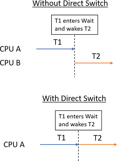
The scheduler has no way of knowing that the first thread (T1 in Figure 4-13) is about to enter a wait state after signaling some synchronization object that the second thread (T2) is waiting on. Therefore, a special function must be called to let the scheduler know that this is the case (atomic signal and wait).
If possible, the KiDirectSwitchThread function performs the actual switch. It’s called by KiExitDispatcher if passed a flag indicating to use Direct Switch if possible. Priority donation, in which the first thread’s priority is “donated” to the second thread (if the latter’s priority is lower than the former), is applied if specified by yet another bit flag to KiExitDispatcher. In the current implementation, these two flags are always specified together (or none at all), meaning in any Direct Switch attempt, priority donation is attempted as well. Direct Switch can fail—for example, if the target thread’s affinity precludes it from running on the current processor. However, if it succeeds, the quantum of the first thread is transferred to the target thread and the first thread loses its remaining quantum.
Direct Switch is currently used in the following scenarios:
![]() If a thread calls the
If a thread calls the SignalObjectAndWait Windows API (or its kernel equivalent NtSignalAndWaitForSingleObject)
![]() ALPC (described in Chapter 8 in Part 2)
ALPC (described in Chapter 8 in Part 2)
![]() Synchronous remote procedure call (RPC) calls
Synchronous remote procedure call (RPC) calls
![]() COM remote calls (currently MTA [multithreaded apartment] to MTA only)
COM remote calls (currently MTA [multithreaded apartment] to MTA only)
Scheduling scenarios
Windows answers the question of “Who gets the CPU?” based on thread priority, but how does this approach work in practice? The following sections illustrate just how priority-driven preemptive multitasking works on the thread level.
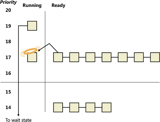
Voluntary switch
A thread might voluntarily relinquish use of the processor by entering a wait state on some object (such as an event, a mutex, a semaphore, an I/O completion port, a process, a thread, and so on) by calling one of the Windows wait functions such as WaitForSingleObject or WaitForMultipleObjects. (Waiting for objects is described in more detail in Chapter 8 in Part 2.)
Figure 4-14 illustrates a thread entering a wait state and Windows selecting a new thread to run. In Figure 4-14, the top block (thread) is voluntarily relinquishing the processor so that the next thread in the ready queue can run. (This is represented by the halo it has when in the Running column.) Although it might appear from this figure that the relinquishing thread’s priority is being reduced, it’s not. It’s just being moved to the wait queue of the objects the thread is waiting for.
Preemption
In this scheduling scenario, a lower-priority thread is preempted when a higher-priority thread becomes ready to run. This situation might occur for a couple of reasons:
![]() A higher-priority thread’s wait completes (the event that the other thread was waiting for has occurred).
A higher-priority thread’s wait completes (the event that the other thread was waiting for has occurred).
![]() A thread priority is increased or decreased.
A thread priority is increased or decreased.
In either of these cases, Windows must determine whether the currently running thread should continue to run or be preempted to allow a higher-priority thread to run.
![]() Note
Note
Threads running in user mode can preempt threads running in kernel mode. The mode in which the thread is running doesn’t matter; the thread priority is the determining factor.
When a thread is preempted, it is put at the head of the ready queue for the priority it was running at (see Figure 4-15).
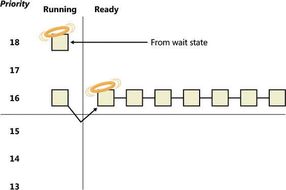
In Figure 4-15, a thread with priority 18 emerges from a wait state and repossesses the CPU, causing the thread that had been running (at priority 16) to be bumped to the head of the ready queue. Notice that the bumped thread doesn’t go to the end of the queue. Rather, it goes to the beginning. When the preempting thread has finished running, the bumped thread can complete its quantum.
Quantum end
When the running thread exhausts its CPU quantum, Windows must determine whether the thread’s priority should be decremented and then whether another thread should be scheduled on the processor.
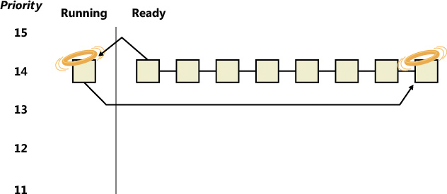
If the thread priority is reduced (for example, because of some boost it received before), Windows looks for a more appropriate thread to schedule, such as one in a ready queue with a higher priority than the new priority for the currently running thread. If the thread priority isn’t reduced and there are other threads in the ready queue at the same priority level, Windows selects the next thread in the ready queue at that same priority level. It then moves the previously running thread to the tail of that queue, giving it a new quantum value and changing its state from running to ready. This is illustrated in Figure 4-16. If no other thread of the same priority is ready to run, the thread gets to run for another quantum.
As you saw, instead of simply relying on a clock interval timer–based quantum to schedule threads, Windows uses an accurate CPU clock cycle count to maintain quantum targets. Windows also uses this count to determine whether quantum end is currently appropriate for the thread—something that might have happened previously and is important to discuss.
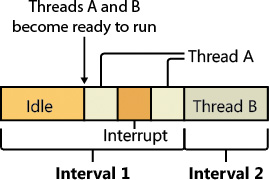
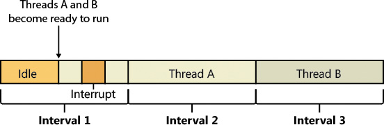
Using a scheduling model that relies only on the clock interval timer, the following situation can occur:
![]() Threads A and B become ready to run during the middle of an interval. (Scheduling code runs not just at each clock interval, so this is often the case.)
Threads A and B become ready to run during the middle of an interval. (Scheduling code runs not just at each clock interval, so this is often the case.)
![]() Thread A starts running but is interrupted for a while. The time spent handling the interrupt is charged to the thread.
Thread A starts running but is interrupted for a while. The time spent handling the interrupt is charged to the thread.
![]() Interrupt processing finishes and thread A starts running again, but it quickly hits the next clock interval. The scheduler can assume only that thread A had been running all this time and now switches to thread B.
Interrupt processing finishes and thread A starts running again, but it quickly hits the next clock interval. The scheduler can assume only that thread A had been running all this time and now switches to thread B.
![]() Thread B starts running and has a chance to run for a full clock interval (barring preemption or interrupt handling).
Thread B starts running and has a chance to run for a full clock interval (barring preemption or interrupt handling).
In this scenario, thread A was unfairly penalized in two different ways. First, the time it spent handling a device interrupt was counted against its own CPU time, even though the thread probably had nothing to do with the interrupt. (Interrupts are handled in the context of whichever thread was running at the time, as discussed in Chapter 6.) It was also unfairly penalized for the time the system was idling inside that clock interval before it was scheduled. Figure 4-17 illustrates this scenario.
Windows keeps an accurate count of the exact number of CPU clock cycles spent doing work that the thread was scheduled to do (which means excluding interrupts). It also keeps a quantum target of clock cycles that should have been spent by the thread at the end of its quantum. Therefore, both of the unfair decisions that would have been made against thread A as described in the preceding paragraph will not happen in Windows. Instead, the following situation occurs:
![]() Threads A and B become ready to run during the middle of an interval.
Threads A and B become ready to run during the middle of an interval.
![]() Thread A starts running but is interrupted for a while. The CPU clock cycles spent handling the interrupt are not charged to the thread.
Thread A starts running but is interrupted for a while. The CPU clock cycles spent handling the interrupt are not charged to the thread.
![]() Interrupt processing finishes and thread A starts running again, but it quickly hits the next clock interval. The scheduler looks at the number of CPU clock cycles charged to the thread and compares them to the expected CPU clock cycles that should have been charged at quantum end.
Interrupt processing finishes and thread A starts running again, but it quickly hits the next clock interval. The scheduler looks at the number of CPU clock cycles charged to the thread and compares them to the expected CPU clock cycles that should have been charged at quantum end.
![]() Because the former number is much smaller than it should be, the scheduler assumes that thread A started running in the middle of a clock interval and might have been additionally interrupted.
Because the former number is much smaller than it should be, the scheduler assumes that thread A started running in the middle of a clock interval and might have been additionally interrupted.
![]() Thread A gets its quantum increased by another clock interval, and the quantum target is recalculated. Thread A now has its chance to run for a full clock interval.
Thread A gets its quantum increased by another clock interval, and the quantum target is recalculated. Thread A now has its chance to run for a full clock interval.
![]() At the next clock interval, thread A has finished its quantum, and thread B now gets a chance to run.
At the next clock interval, thread A has finished its quantum, and thread B now gets a chance to run.
Figure 4-18 illustrates this scenario.
Termination
When a thread finishes running (either because it returned from its main routine, called ExitThread, or was killed with TerminateThread), it moves from the running state to the terminated state. If there are no handles open on the thread object, the thread is removed from the process thread list and the associated data structures are deallocated and released.
Idle threads
When no runnable thread exists on a CPU, Windows dispatches that CPU’s idle thread. Each CPU has its own dedicated idle thread. This is because on a multiprocessor system, one CPU can be executing a thread while other CPUs might have no threads to execute. Each CPU’s idle thread is found via a pointer in that CPU’s PRCB.
All the idle threads belong to the idle process. The idle process and idle threads are special cases in many ways. They are, of course, represented by EPROCESS/KPROCESS and ETHREAD/KTHREAD structures, but they are not executive manager processes and thread objects. Nor is the idle process on the system process list. (This is why it does not appear in the output of the kernel debugger’s !process 0 0 command.) However, the idle thread or threads and their process can be found in other ways.
The preceding experiment shows some of the anomalies associated with the idle process and its threads. The debugger indicates an Image name of Idle (which comes from the EPROCESS structure’s ImageFileName member), but various Windows utilities report the idle process using different names. Task Manager and Process Explorer call it System Idle Process, while tlist calls it System Process. The process ID and thread IDs (the client IDs, or Cid in the debugger’s output) are 0, as are the PEB and TEB pointers and potentially many other fields in the idle process or its threads. Because the idle process has no user-mode address space and its threads execute no user-mode code, they have no need of the various data required to manage a user-mode environment. Also, the idle process is not an object-manager process object, and its idle threads are not object-manager thread objects. Instead, the initial idle thread and idle process structures are statically allocated and used to bootstrap the system before the process manager and the object manager are initialized. Subsequent idle thread structures are allocated dynamically (as simple allocations from a non-paged pool, bypassing the object manager) as additional processors are brought online. Once process management initializes, it uses the special variable PsIdleProcess to refer to the idle process.
Perhaps the most interesting anomaly regarding the idle process is that Windows reports the priority of the idle threads as 0. In reality, however, the values of the idle threads’ priority members are irrelevant because these threads are selected for dispatching only when there are no other threads to run. Their priority is never compared with that of any other thread. Nor is it used to put an idle thread on a ready queue, as idle threads are never part of any ready queues. (Only one thread per Windows system is actually running at priority 0—the zero page thread, explained in Chapter 5.)
Just as the idle threads are special cases in terms of selection for execution, they are also special cases for preemption. The idle thread’s routine, KiIdleLoop, performs a number of operations that preclude its being preempted by another thread in the usual fashion. When no non-idle threads are available to run on a processor, that processor is marked as idle in its PRCB. After that, if a thread is selected for execution on the idle processor, the thread’s address is stored in the NextThread pointer of the idle processor’s PRCB. The idle thread checks this pointer on each pass through its loop.
Although some details of the flow vary between architectures (this is one of the few routines written in assembly and not in C), the basic sequence of operations of the idle thread is as follows:
1. The idle thread briefly enables interrupts, allowing any pending interrupts to be delivered, and then disables them (using the STI and CLI instructions on x86 and x64 processors). This is desirable because significant parts of the idle thread execute with interrupts disabled.
2. On the debug build on some architectures, the idle thread checks whether there is a kernel debugger trying to break into the system. If so, it gives it access.
3. The idle thread checks whether any DPCs (described in Chapter 6) are pending on the processor. DPCs could be pending if a DPC interrupt was not generated when they were queued. If DPCs are pending, the idle loop calls KiRetireDpcList to deliver them. This will also perform timer expiration, as well as deferred ready processing; the latter is explained in the upcoming “Multiprocessor systems” section. KiRetireDpcList must be entered with interrupts disabled, which is why interrupts are left disabled at the end of step 1. KiRetireDpcList exits with interrupts disabled as well.
4. The idle thread checks whether quantum end processing has been requested. If so, KiQuantum-End is called to process the request.
5. The idle thread checks whether a thread has been selected to run next on the processor. If so, it dispatches that thread. This could be the case if, for example, a DPC or timer expiration processed in step 3 resolved the wait of a waiting thread, or if another processor selected a thread for this processor to run while it was already in the idle loop.
6. If requested, the idle thread checks for threads ready to run on other processors and, if possible, schedules one of them locally. (This operation is explained in the upcoming “Idle scheduler” section).
7. The idle thread calls the registered power-management processor idle routine (in case any power-management functions need to be performed), which is either in the processor power driver (such as intelppm.sys) or in the HAL if such a driver is unavailable.
Thread suspension
Threads can be suspended and resumed explicitly with the SuspendThread and ResumeThread API functions, respectively. Every thread has a suspend count, which is incremented by suspension and decremented by resuming. If the count is 0, the thread is free to execute. Otherwise, it will not execute.
Suspension works by queuing a kernel APC to the thread. When the thread is switched in to execute, the APC is executed first. This puts the thread in a wait state on event that is signaled when the thread is finally resumed.
This suspension mechanism has a noticeable drawback if the thread is in a wait state while a suspension request comes in, because it means that the thread needs to wake up just to be suspended. This can result in a kernel stack inswap (if the thread’s kernel stack was swapped out). Windows 8.1 and Server 2012 R2 added a mechanism called Lightweight Suspend to allow for the suspension of a thread that is in a wait state not by using the APC mechanism, but by directly manipulating the thread’s object in memory and marking it as suspended.
(Deep) freeze
Freezing is a mechanism by which processes enter a suspended state that cannot be changed by calling ResumeThread on threads in the process. This is useful when the system needs to suspend a UWP app. This happens when a Windows app goes to the background—for example, because another app comes to the foreground in Tablet mode or the app is minimized in Desktop mode. In this case, the system gives to the app roughly five seconds to do work, typically to save application state. Saving state is important because Windows apps may be killed without any notice if memory resources become low. If the app is killed, the state can be reloaded on the next launch and the user would have the perception that the app never really went away. Freezing a process means suspending all threads in such a way that ResumeThread is not able to wake. A flag in the KTHREAD structure indicates whether a thread is frozen. For a thread to be able to execute, its suspend count must be 0 and the frozen flag must be clear.
Deep freeze adds another constraint: Newly created threads in the process cannot start as well. For example, if a call to CreateRemoteThreadEx is used to create a new thread in a deep-frozen process, the thread will be frozen before actually starting. This is the typical usage of the freezing capability.
Process- and thread-freezing functionality is not exposed directly to user mode. It is used internally by the Process State Manager (PSM) service that is responsible for issuing the requests to the kernel for deep freezing and thawing (unfreezing).
You can also freeze processes using jobs. The ability to freeze and unfreeze a job is not publicly documented, but it’s possible to do using the standard NtSetInformationJobObject system call. This is typically used for Windows apps, as all Windows apps processes are contained in jobs. Such a job may contain a single process (the Windows app itself), but it can also contain background task-hosting processes related to the same Window app so that freezing or thawing (unfreezing) all processes under that job can be done in a single stroke. (See Chapter 8 in Part 2 for more on Windows apps.)
Thread selection
Whenever a logical processor needs to pick the next thread to run, it calls the KiSelectNextThread scheduler function. This can happen in a variety of scenarios:
![]() A hard affinity change has occurred, making the currently running or standby thread ineligible for execution on its selected logical processor. Therefore, another must be chosen.
A hard affinity change has occurred, making the currently running or standby thread ineligible for execution on its selected logical processor. Therefore, another must be chosen.
![]() The currently running thread reached its quantum end, and the Symmetric Multithreading (SMT) set it was running on has become busy while other SMT sets within the ideal node are fully idle. (Symmetric Multithreading is the technical name for the hyper-threading technology described in Chapter 2.) The scheduler performs a quantum-end migration of the current thread, so another must be chosen.
The currently running thread reached its quantum end, and the Symmetric Multithreading (SMT) set it was running on has become busy while other SMT sets within the ideal node are fully idle. (Symmetric Multithreading is the technical name for the hyper-threading technology described in Chapter 2.) The scheduler performs a quantum-end migration of the current thread, so another must be chosen.
![]() A wait operation has finished, and there were pending scheduling operations in the wait status register (in other words, the priority and/or affinity bits were set).
A wait operation has finished, and there were pending scheduling operations in the wait status register (in other words, the priority and/or affinity bits were set).
In these scenarios, the behavior of the scheduler is as follows:
![]() The scheduler calls
The scheduler calls KiSelectReadyThreadEx to search for the next ready thread that the processor should run and check whether one was found.
![]() If a ready thread was not found, the idle scheduler is enabled, and the idle thread is selected for execution. If a ready thread was found, it is put in the ready state in the local or shared ready queue, as appropriate.
If a ready thread was not found, the idle scheduler is enabled, and the idle thread is selected for execution. If a ready thread was found, it is put in the ready state in the local or shared ready queue, as appropriate.
The KiSelectNextThread operation is performed only when the logical processor needs to pick—but not yet run—the next schedulable thread (which is why the thread will enter the Ready state). Other times, however, the logical processor is interested in immediately running the next ready thread or performing another action if one is not available (instead of going idle), such as when the following occurs:
![]() A priority change causes the current standby or running thread to no longer be the highest-priority ready thread on its selected logical processor, meaning that a higher priority ready thread must now run.
A priority change causes the current standby or running thread to no longer be the highest-priority ready thread on its selected logical processor, meaning that a higher priority ready thread must now run.
![]() The thread has explicitly yielded with
The thread has explicitly yielded with YieldProcessor or NtYieldExecution and another thread might be ready for execution.
![]() The quantum of the current thread has expired, and other threads at the same priority level need their chance to run as well.
The quantum of the current thread has expired, and other threads at the same priority level need their chance to run as well.
![]() A thread has lost its priority boost, causing a similar priority change to the scenario just described.
A thread has lost its priority boost, causing a similar priority change to the scenario just described.
![]() The idle scheduler is running and needs to check whether a ready thread has not appeared in the interval between when the idle scheduling was requested and the idle scheduler ran.
The idle scheduler is running and needs to check whether a ready thread has not appeared in the interval between when the idle scheduling was requested and the idle scheduler ran.
A simple way to remember the difference between which routine runs is to check whether the logical processor must run a different thread (in which case KiSelectNextThread is called) or if it should if possible run a different thread (in which case KiSelectReadyThreadEx is called). In either case, because each processor belongs to a shared ready queue (pointed to by the KPRCB), KiSelectReady-ThreadEx can simply check the current logical processor’s (LP’s) queues, removing the first highest-priority thread that it finds unless this priority is lower than the one of the currently running thread (depending on whether the current thread is still allowed to run, which would not be the case in the KiSelectNextThread scenario). If there is no higher-priority thread (or no threads are ready at all), no thread is returned.
Idle scheduler
Whenever the idle thread runs, it checks whether idle scheduling has been enabled. If so, the idle thread begins scanning other processors’ ready queues for threads it can run by calling KiSearchForNewThread. The run-time costs associated with this operation are not charged as idle thread time, but are instead charged as interrupt and DPC time (charged to the processor), so idle scheduling time is considered system time. The KiSearchForNewThread algorithm, which is based on the functions described earlier in this section, is explained shortly.
Multiprocessor systems
On a uniprocessor system, scheduling is relatively simple: The highest-priority thread that wants to run is always running. On a multiprocessor system, it is more complex. This is because Windows attempts to schedule threads on the most optimal processor for the thread, taking into account the thread’s preferred and previous processors as well as the configuration of the multiprocessor system. Therefore, although Windows attempts to schedule the highest-priority runnable threads on all available CPUs, it guarantees only to be running one of the highest-priority threads somewhere. With shared ready queues (for threads with no affinity restrictions), the guarantee is stronger. Each shared group of processors is running at least one of the highest-priority threads.
Before we describe the specific algorithms used to choose which threads run where and when, let’s examine the additional information Windows maintains to track thread and processor state on multiprocessor systems and the three different types of multiprocessor systems supported by Windows (SMT, multicore, and NUMA).
Package sets and SMT sets
Windows uses five fields in the KPRCB to determine correct scheduling decisions when dealing with logical processor topologies. The first field, CoresPerPhysicalProcessor, determines whether this logical processor is part of a multicore package. It’s computed from the CPUID returned by the processor and rounded to a power of 2. The second field, LogicalProcessorsPerCore, determines whether the logical processor is part of an SMT set, such as on an Intel processor with hyper-threading enabled, and is also queried through CPUID and rounded. Multiplying these two numbers yields the number of logical processors per package, or an actual physical processor that fits into a socket. With these numbers, each PRCB can then populate its PackageProcessorSet value. This is the affinity mask describing which other logical processors within this group (because packages are constrained to a group) belong to the same physical processor. Similarly, the CoreProcessorSet value connects other logical processors to the same core, also called an SMT set. Finally, the GroupSetMember value defines which bitmask within the current processor group identifies this very logical processor. For example, the logical processor 3 normally has a GroupSetMember value of 8 (which equals 2 to the third power).
NUMA systems
Another type of multiprocessor system supported by Windows is one with a non-uniform memory architecture (NUMA). In a NUMA system, processors are grouped together in smaller units called nodes. Each node has its own processors and memory and is connected to the larger system through a cache-coherent interconnect bus. These systems are called non-uniform because each node has its own local high-speed memory. Although any processor in any node can access all of memory, node-local memory is much faster to access.
The kernel maintains information about each node in a NUMA system in a data structure called KNODE. The kernel variable KeNodeBlock is an array of pointers to the KNODE structures for each node. You can reveal the format of the KNODE structure using the dt command in the kernel debugger, as shown here:
lkd> dt nt!_KNODE
+0x000 IdleNonParkedCpuSet : Uint8B
+0x008 IdleSmtSet : Uint8B
+0x010 IdleCpuSet : Uint8B
+0x040 DeepIdleSet : Uint8B
+0x048 IdleConstrainedSet : Uint8B
+0x050 NonParkedSet : Uint8B
+0x058 ParkLock : Int4B
+0x05c Seed : Uint4B
+0x080 SiblingMask : Uint4B
+0x088 Affinity : _GROUP_AFFINITY
+0x088 AffinityFill : [10] UChar
+0x092 NodeNumber : Uint2B
+0x094 PrimaryNodeNumber : Uint2B
+0x096 Stride : UChar
+0x097 Spare0 : UChar
+0x098 SharedReadyQueueLeaders : Uint8B
+0x0a0 ProximityId : Uint4B
+0x0a4 Lowest : Uint4B
+0x0a8 Highest : Uint4B
+0x0ac MaximumProcessors : UChar
+0x0ad Flags : _flags
+0x0ae Spare10 : UChar
+0x0b0 HeteroSets : [5] _KHETERO_PROCESSOR_SET
EXPERIMENT: Viewing NUMA information
1. Click Start, type hyper, and click the Hyper-V Manager option.
2. Make sure the VM is powered off. Otherwise the following changes cannot be made.
3. Right-click the VM in Hyper-V Manager and select Settings to open the VM’s settings.
4. Click the Memory node and make sure Dynamic Memory is unchecked.
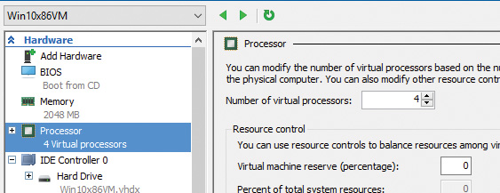
5. Click the Processor node and enter 4 in the Number of Virtual Processors box:
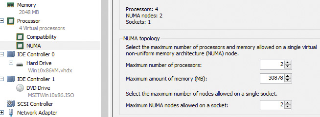
6. Expand the Processor node and select the NUMA sub-node.
7. Enter 2 in the Maximum Number of Processors and Maximum NUMA Nodes Allowed on a Socket boxes:
8. Click OK to save the settings.
9. Power up the VM.
10. Use a kernel debugger to issue the !numa command. Here’s an example of output for the previously configured VM:
2: kd> !numa
NUMA Summary:
------------
Number of NUMA nodes : 2
Number of Processors : 4
unable to get nt!MmAvailablePages
MmAvailablePages : 0x00000000
KeActiveProcessors :
****---------------------------- (0000000f)
NODE 0 (FFFFFFFF820510C0):
Group : 0 (Assigned, Committed, Assignment Adjustable)
ProcessorMask : **------------------------------ (00000003)
ProximityId : 0
Capacity : 2
Seed : 0x00000001
IdleCpuSet : 00000003
IdleSmtSet : 00000003
NonParkedSet : 00000003
Unable to get MiNodeInformation
NODE 1 (FFFFFFFF8719E0C0):
Group : 0 (Assigned, Committed, Assignment Adjustable)
ProcessorMask : --**---------------------------- (0000000c)
ProximityId : 1
Capacity : 2
Seed : 0x00000003
IdleCpuSet : 00000008
IdleSmtSet : 00000008
NonParkedSet : 0000000c
Unable to get MiNodeInformation
Applications that want to gain the most performance out of NUMA systems can set the affinity mask to restrict a process to the processors in a specific node, although Windows already restricts nearly all threads to a single NUMA node due to its NUMA-aware scheduling algorithms.
How the scheduling algorithms account for NUMA systems is covered later in this chapter in the section “Processor selection.” (The optimizations in the memory manager to take advantage of node-local memory are covered in Chapter 5.)
Processor group assignment
While querying the topology of the system to build the various relationships between logical processors, SMT sets, multicore packages, and physical sockets, Windows assigns processors to an appropriate group that will describe their affinity (through the extended affinity mask seen earlier). This work is done by the KePerformGroupConfiguration routine, which is called during initialization before any other phase 1 work is done. The steps of this process are as follows:
1. The function queries all detected nodes (KeNumberNodes) and computes the capacity of each node—that is, how many logical processors can be part of the node. This value is stored in MaximumProcessors in the KeNodeBlock array, which identifies all NUMA nodes on the system. If the system supports NUMA proximity IDs, the proximity ID is queried for each node and saved in the node block.
2. The NUMA distance array is allocated (KeNodeDistance) and the distance between each NUMA node is computed.
The next series of steps deal with specific user-configuration options that override default NUMA assignments. For example, consider a system with Hyper-V installed and with the hypervisor configured to auto-start. If the CPU does not support the extended hypervisor interface, then only one processor group will be enabled, and all NUMA nodes (that can fit) will be associated with group 0. Therefore, in this case, Hyper-V cannot take advantage of machines with more than 64 processors.
3. The function checks whether any static group assignment data was passed by the loader (and thus configured by the user). This data specifies the proximity information and group assignment for each NUMA node.
![]() Note
Note
Users dealing with large NUMA servers who might need custom control of proximity information and group assignments for testing or validation purposes can enter this data through the Group Assignment and Node Distance registry values. These are found in the HKLM\SYSTEM\CurrentControlSet\Control\NUMA registry key. The exact format of this data includes a count followed by an array of proximity IDs and group assignments, which are all 32-bit values.
4. Before treating this data as valid, the kernel queries the proximity ID to match the node number and then associates group numbers as requested. It then makes sure that NUMA node 0 is associated with group 0, and that the capacity for all NUMA nodes is consistent with the group size. Finally, the function checks how many groups still have remaining capacity.
![]() Note
Note
NUMA node 0 is always assigned to group 0, no matter what.
5. The kernel dynamically attempts to assign NUMA nodes to groups while respecting any statically configured nodes if passed in as just described. Normally, the kernel tries to minimize the number of groups created, combining as many NUMA nodes as possible per group. However, if this behavior is not desired, it can be configured differently with the /MAXGROUP loader parameter, configured through the maxgroup BCD option. Turning this value on overrides the default behavior and causes the algorithm to spread as many NUMA nodes as possible into as many groups as possible, while respecting that the currently implemented group limit is 20. If there is only one node, or if all nodes can fit into a single group (and maxgroup is off), the system performs the default setting of assigning all nodes to group 0.
6. If there is more than one node, Windows checks the static NUMA node distances (if any). It then sorts all the nodes by their capacity so that the largest nodes come first. In the group-minimization mode, the kernel figures out the maximum processors there can be by adding up all the capacities. By dividing that by the number of processors per group, the kernel assumes there will be this many total groups on the machine (limited to a maximum of 20). In group-maximization mode, the initial estimate is that there will be as many groups as nodes (limited again to 20).
7. The kernel begins the final assignment process. All fixed assignments from earlier are now committed and groups are created for those assignments.
8. All the NUMA nodes are reshuffled to minimize the distance between the different nodes within a group. In other words, closer nodes are put in the same group and sorted by distance.
9. The same process is performed for any dynamically configured node to group assignments.
10. Any remaining empty nodes are assigned to group 0.
Logical processors per group
Generally, Windows assigns 64 processors per group. But you can also customize this configuration by using different load options such as the /GROUPSIZE option, which is configured through the groupsize BCD element. By specifying a number that is a power of 2, you can force groups to contain fewer processors than normal for purposes such as testing group awareness in the system. For example, a system with eight logical processors can be made to appear to have one, two, or four groups. To force the issue, the /FORCEGROUPAWARE option (BCD element groupaware) causes the kernel to avoid group 0 whenever possible, assigning the highest group number available in actions such as thread and DPC affinity selection and process group assignment. You should avoid setting a group size of 1 because this will force almost all applications on the system to behave as if they’re running on a uniprocessor machine. This is because the kernel sets the affinity mask of a given process to span only one group until the application requests otherwise (which most applications will not do).
In the edge case where the number of logical processors in a package cannot fit into a single group, Windows adjusts these numbers so that a package can fit into a single group. It does so by shrinking the CoresPerPhysicalProcessor number and, if the SMT cannot fit, the LogicalProcessorsPerCore number. The exception to this rule is if the system actually contains multiple NUMA nodes within a single package (uncommon, but possible). In these multi-chip modules (MCMs), two sets of cores as well as two memory controllers are on the same die/package. If the ACPI Static Resource Affinity Table (SRAT) defines the MCM as having two NUMA nodes, Windows might associate the two nodes with two different groups (depending on group-configuration algorithms). In this scenario, the MCM package would span more than one group.
Other than causing significant driver and application compatibility problems—which they are designed to identify and root out, when used by developers—these options have an even greater impact on the machine: They force NUMA behaviors even on a non-NUMA machine. This is because Windows will never allow a NUMA node to span multiple groups, as was shown in the assignment algorithms. So, if the kernel is creating artificially small groups, those two groups must each have their own NUMA node. For example, on a quad-core processor with a group size of 2, this will create two groups, and thus two NUMA nodes, which will be subnodes of the main node. This will affect scheduling and memory-management policies in the same way a true NUMA system would, which can be useful for testing.
Logical processor state
In addition to the shared and local ready queues and summaries, Windows maintains two bitmasks that track the state of the processors on the system. (How these bitmasks are used is explained in the upcoming “Processor selection” section.) Following are the bitmasks that Windows maintains:
![]()
KeActiveProcessors This is the active processor mask, which has a bit set for each usable processor on the system. These might be fewer than the number of actual processors if the licensing limits of the version of Windows running supports fewer than the number of available physical processors. Use the KeRegisteredProcessors variable to see how many processors are actually licensed on the machine. In this instance, processors refers to physical packages.
![]()
KeMaximumProcessors This is the maximum number of logical processors (including all future possible dynamic processor additions) bounded within the licensing limit. It also reveals any platform limitations that are queried by calling the HAL and checking with the ACPI SRAT table, if any.
Part of the node’s data (KNODE) is the set of idle CPUs in this node (the IdleCpuSet member), idle CPUs that are not parked (IdleNonParkedCpuSet), and idle SMT sets (IdleSmtSet).
Scheduler scalability
On a multiprocessor system, one processor might need to modify another processor’s per-CPU scheduling data structures—for example, inserting a thread that would like to run on a certain processor. For this reason, you synchronize these structures by using a per-PRCB queued spinlock, which is held at DISPATCH_LEVEL. Thus, thread selection can occur while locking only an individual processor’s PRCB. If needed, one more processor’s PRCB can also be locked, such as in scenarios of thread stealing (described later). Thread context switching is also synchronized by using a finer-grained per-thread spinlock.
There is also a per-CPU list of threads in the deferred ready state (DeferredReadyListHead). These represent threads that are ready to run but have not yet been readied for execution; the actual ready operation has been deferred to a more appropriate time. Because each processor manipulates only its own per-processor deferred ready list, this list is not synchronized by the PRCB spinlock. The deferred ready thread list is processed by KiProcessDeferredReadyList after a function has already done modifications to process or thread affinity, priority (including due to priority boosting), or quantum values.
This function calls KiDeferredReadyThread for each thread on the list, which performs the algorithm shown later in this chapter in the “Processor selection” section. This could cause the thread to run immediately; to be put on the ready list of the processor; or, if the processor is unavailable, to be potentially put on a different processor’s deferred ready list, in a standby state or immediately executed. This property is used by the core parking engine when parking a core: All threads are put into the deferred ready list, and it is then processed. Because KiDeferredReadyThread skips parked cores (
as will be shown), it causes all of this processor’s threads to wind up on other processors.
Affinity
Each thread has an affinity mask that specifies the processors on which the thread is allowed to run. The thread affinity mask is inherited from the process affinity mask. By default, all processes (and therefore all threads) begin with an affinity mask that is equal to the set of all active processors on their assigned group. In other words, the system is free to schedule all threads on any available processor within the group associated with the process. However, to optimize throughput, partition workloads to a specific set of processors, or both, applications can choose to change the affinity mask for a thread. This can be done at several levels:
![]() By calling the
By calling the SetThreadAffinityMask function to set the affinity for an individual thread.
![]() By calling the
By calling the SetProcessAffinityMask function to set the affinity for all the threads in a process.
![]() Task Manager and Process Explorer provide a GUI to this function. To access it, right-click a process and choose Set Affinity. In addition, the Psexec tool (from Sysinternals) provides a command-line interface to this function. (See the
Task Manager and Process Explorer provide a GUI to this function. To access it, right-click a process and choose Set Affinity. In addition, the Psexec tool (from Sysinternals) provides a command-line interface to this function. (See the –a switch in its help output.)
![]() By making a process a member of a job that has a job-wide affinity mask set using the
By making a process a member of a job that has a job-wide affinity mask set using the SetInformationJobObject function (described in Chapter 3).
![]() By specifying an affinity mask in the image header when compiling the application.
By specifying an affinity mask in the image header when compiling the application.
![]() Tip
Tip
For a detailed specification of the Windows images format, search for Portable Executable and Common Object File Format Specification on http://msdn.microsoft.com.
An image can also have the uniprocessor flag set at link time. If this flag is set, the system chooses a single processor at process-creation time (MmRotatingProcessorNumber) and assigns that as the process affinity mask, starting with the first processor and then going round-robin across all the processors within the group. For example, on a dual-processor system, the first time an image marked with the uniprocessor flag is launched, it is assigned to CPU 0; the second time, CPU 1; the third time, CPU 0; the fourth time, CPU 1; and so on. This flag can be useful as a temporary workaround for programs that have multithreaded synchronization bugs that surface on multiprocessor systems due to race conditions but not on uniprocessor systems. If an image exhibits such symptoms and is unsigned, you can add the flag manually editing the image header with a Portable Executable (PE) image-editing tool. A better solution, also compatible with signed executables, is to use the Microsoft Application Compatibility Toolkit and add a shim to force the compatibility database to mark the image as uniprocessor-only at launch time.
EXPERIMENT: Viewing and changing process affinity
1. Run the command prompt (Cmd.exe).
2. Run Task Manager or Process Explorer and find the Cmd.exe process in the process list.
3. Right-click the process and select Set Affinity. A list of processors should be displayed. For example, on a system with eight logical processes, you will see this:
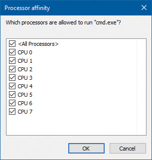
4. Select a subset of the available processors on the system and click OK. The process’s threads are now restricted to run on the processors you just selected.
5. At the command prompt, type Notepad to run Notepad.exe.
6. Go back to Task Manager or Process Explorer and find the new Notepad process.
7. Right-click the process and choose Affinity. You should see the same list of processors you chose for the command-prompt process. This is because processes inherit their affinity settings from their parent.
Windows won’t move a running thread that could run on a different processor from one CPU to a second processor to permit a thread with an affinity for the first processor to run on the first processor. For example, consider this scenario: CPU 0 is running a priority 8 thread that can run on any processor, and CPU 1 is running a priority 4 thread that can run on any processor. A priority 6 thread that can run on only CPU 0 becomes ready. What happens? Windows won’t move the priority 8 thread from CPU 0 to CPU 1 (preempting the priority 4 thread) so that the priority 6 thread can run; the priority 6 thread must stay in the ready state. Therefore, changing the affinity mask for a process or thread can result in threads getting less CPU time than they normally would because Windows is restricted from running the thread on certain processors. Therefore, setting affinity should be done with extreme care. In most cases, it is optimal to let Windows decide which threads run where.
Extended affinity mask
To support more than 64 processors, which is the limit enforced by the original affinity mask structure (composed of 64 bits on a 64-bit system), Windows uses an extended affinity mask, KAFFINITY_EX. This is an array of affinity masks, one for each supported processor group (currently defined at 20). When the scheduler needs to refer to a processor in the extended affinity masks, it first de-references the correct bitmask by using its group number and then accesses the resulting affinity directly. In the kernel API, extended affinity masks are not exposed; instead, the caller of the API inputs the group number as a parameter and receives the legacy affinity mask for that group. In the Windows API, on the other hand, only information about a single group can usually be queried, which is the group of the currently running thread (which is fixed).
The extended affinity mask and its underlying functionality are also how a process can escape the boundaries of its original assigned processor group. By using the extended affinity APIs, threads in a process can choose affinity masks on other processor groups. For example, if a process has four threads and the machine has 256 processors, thread 1 can run on processor 4, thread 2 can run on processor 68, thread 3 on processor 132, and thread 4 on processor 196, if each thread set an affinity mask of 0x10 (0b10000 in binary) on groups 0, 1, 2, and 3. Alternatively, the threads can each set an affinity of all 1 bits (0xFFFF...) for their given group, and the process then can execute its threads on any available processor on the system (with the limitation that each thread is restricted to running within its own group only).
You can take advantage of extended affinity at creation time by specifying a group number in the thread attribute list (PROC_THREAD_ATTRIBUTE_GROUP_AFFINITY) when creating a new thread or by calling SetThreadGroupAffinity on an existing thread.
System affinity mask
Windows drivers usually execute in the context of the calling thread or an arbitrary thread (that is, not in the safe confines of the System process). Therefore, currently running driver code might be subject to affinity rules set by the application developer. These are not currently relevant to the driver code and might even prevent correct processing of interrupts and other queued work. Driver developers therefore have a mechanism to temporarily bypass user thread affinity settings, by using the KeSetSystemAffinityThread(Ex)/KeSetSystemGroupAffinityThread and KeRevertToUser-AffinityThread(Ex)/KeRevertToUserGroupAffinityThread APIs.
Ideal and last processor
Each thread has three CPU numbers stored in the kernel thread control block:
![]() Ideal processor This is the preferred processor that this thread should run on.
Ideal processor This is the preferred processor that this thread should run on.
![]() Last processor This is the processor the thread last ran on.
Last processor This is the processor the thread last ran on.
![]() Next processor This is the processor that the thread will be or is already running on.
Next processor This is the processor that the thread will be or is already running on.
The ideal processor for a thread is chosen when a thread is created using a seed in the process control block. The seed is incremented each time a thread is created so that the ideal processor for each new thread in the process rotates through the available processors on the system. For example, the first thread in the first process on the system is assigned an ideal processor of 0 and the second thread in that process is assigned an ideal processor of 1. However, the next process in the system has its first thread’s ideal processor set to 1, the second to 2, and so on. In that way, the threads within each process are spread across the processors. On SMT systems (hyper-threading), the next ideal processor is selected from the next SMT set. For example, on a quad-core, hyper-threaded system, ideal processors for threads in a certain process could be 0, 2, 4, 6, 0, ...; 3, 5, 7, 1, 3, ...; etc. In this way, the threads are spread evenly across the physical processors.
Note that this assumes the threads within a process are doing an equal amount of work. This is typically not the case in a multithreaded process, which normally has one or more housekeeping threads and numerous worker threads. Therefore, a multithreaded application that wants to take full advantage of the platform might find it advantageous to specify the ideal processor numbers for its threads by using the SetThreadIdealProcessor function. To take advantage of processor groups, developers should call SetThreadIdealProcessorEx instead, which allows selection of a group number for the affinity.
In 64-bit Windows, the Stride field in the KNODE is used to balance the assignment of newly created threads within a process. The stride is a scalar number that represents the number of affinity bits within a given NUMA node that must be skipped to attain a new independent logical processor slice, where independent means on another core (if dealing with an SMT system) or another package (if dealing with a non-SMT but multicore system). Because 32-bit Windows doesn’t support large processor-configuration systems, it doesn’t use a stride. It simply selects the next processor number, trying to avoid sharing the same SMT set if possible.
Ideal node
On NUMA systems, when a process is created, an ideal node for the process is selected. The first process is assigned to node 0, the second process to node 1, and so on. Then the ideal processors for the threads in the process are chosen from the process’s ideal node. The ideal processor for the first thread in a process is assigned to the first processor in the node. As additional threads are created in processes with the same ideal node, the next processor is used for the next thread’s ideal processor, and so on.
CPU sets
You’ve seen how affinity (sometimes referred to as hard affinity) can limit threads to certain processors, which is always honored by the scheduler. The ideal processor mechanism tries to run threads on their ideal processors (sometimes referred to as soft affinity), generally expecting to have the thread’s state be part of the processor’s cache. The ideal processor may or may not be used, and it does not prevent the thread from being scheduled on other processors. Both these mechanisms don’t work on system-related activity, such as system threads activity. Also, there is no easy way to set hard affinity to all processes on a system in one stroke. Even walking the process would not work. System processes are generally protected from external affinity changes because they require the PROCESS_SET_INFORMATION access right, which is not granted for protected processes.
Windows 10 and Server 2016 introduce a mechanism called CPU sets. These are a form of affinity that you can set for use by the system as a whole (including system threads activity), processes, and even individual threads. For example, a low-latency audio application may want to use a processor exclusively while the rest of the system is diverted to use other processors. CPU sets provide a way to achieve that.
The documented user mode API is somewhat limited at the time of this writing. GetSystemCpuSet-Information returns an array of SYSTEM_CPU_SET_INFORMATION that contains data for each CPU set. In the current implementation, a CPU set is equivalent to a single CPU. This means the returned array’s length is the number of logical processors on the system. Each CPU set is identified by its ID, which is arbitrarily selected to be 256 (0x100) plus the CPU index (0, 1, ...). These IDs are the ones that must be passed to SetProcessDefaultCpuSets and SetThreadSelectedCpuSets functions to set default CPU sets for a process and a CPU set for a specific thread, respectively.
An example for setting thread CPU set would be for an “important” thread that should not be interrupted if possible. This thread could have a CPU set that contains one CPU, while setting the default process CPU set to include all other CPUs.
One missing function in the Windows API is the ability to reduce the system CPU set. This can be achieved by a call to the NtSetSystemInformation system call. For this to succeed, the caller must have SeIncreaseBasePriorityPrivilege.
1. Download the CpuSet.exe tool from the book’s downloadable resources.
2. Open an administrative command window and navigate to the directory where CPUSET.exe exists.
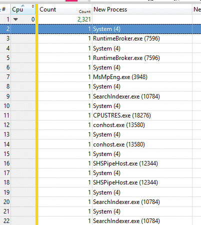
3. At the command window, type cpuset.exe without arguments to see the current system CPU sets. The output should be similar to the following:
System CPU Sets
---------------
Total CPU Sets: 8
CPU Set 0
Id: 256 (0x100)
Group: 0
Logical Processor: 0
Core: 0
Last Level Cache: 0
NUMA Node: 0
Flags: 0 (0x0) Parked: False Allocated: False Realtime: False Tag: 0
CPU Set 1
Id: 257 (0x101)
Group: 0
Logical Processor: 1
Core: 0
Last Level Cache: 0
NUMA Node: 0
Flags: 0 (0x0) Parked: False Allocated: False Realtime: False Tag: 0
...
4. Run CPUSTRES.exe and configure it to run a thread or two with maximum activity level. (Aim for something around 25 percent CPU usage.)
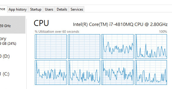
5. Open Task Manager, click the Performance tab, and select the CPU label.
6. Change the CPU graph view to show individual processors (if the view is configured for overall utilization).
7. At the command window, run the following command, replacing the number after -p with the process ID of the CPUSTRES process on your system:
CpuSet.exe -p 18276 -s 3
The -s argument specifies the processor mask to set as the default for the process. Here, 3 means CPU 0 and 1. You should see Task Manager hard at work on these two CPUs:
8. Let’s look at CPU 0 more closely to see what threads it’s running. For this, you’ll use Windows Performance Recorder (WPR) and Windows Performance Analyzer (WPA) from the Windows SDK. Click the Start button, type WPR, and select Windows Performance Recorder. Then accept the elevation prompt. You should see the following dialog box:
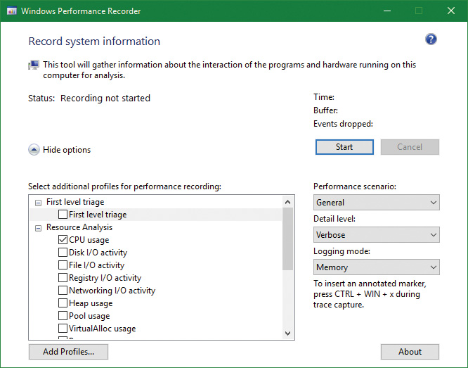
9. The default is to record CPU usage, which is what we want. This tool records Event Tracing for Windows (ETW) events. (See Chapter 8 in Part 2 for more on ETW.) Click the Start button in the dialog box and, after a second or two click the same button, now labeled Save.
10. WPR will suggest a location to save the recorded data. Accept it or change to some other file/folder.
11. After the file is saved, WPR suggests opening the file with WPA. Accept the suggestion.
12. The WPA tool opens and loads the saved file. (WPA is a rich tool, well beyond the scope of this book). On the left, you’ll see the various categories of information captured, something like so:
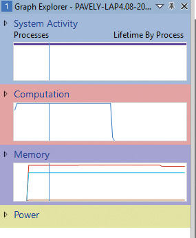
13. Expand the Computation node and then expand the CPU Usage (Precise) node.
14. Double-click the Utilization by CPU graph. It should open in the main display:
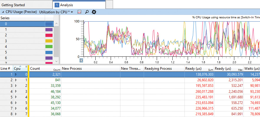
15. At the moment, we’re interested in CPU 0. In the next step, you’ll make CPU 0 work for CPUSTRES only. To begin, expand the CPU 0 node. You should see various processes, including CPUSTRES, but certainly not exclusively:
16. Enter the following command to restrict the system to use all processors except the first. In this system, the number of processors is eight, so a full mask is 255 (0xff). Removing CPU 0 produces 254 (0xfe). Replace the mask with the correct one for your system:
CpuSet.exe -s 0xfe
17. The view in Task Manager should look about the same. Let’s take a closer look at CPU 0. Run WPR again, and record a second or two with the same settings as before.
18. Open the trace in WPA and navigate to Utilization by CPU.
19. Expand CPU 0. You should see CPUSTRES almost exclusively, with the System process appearing occasionally:
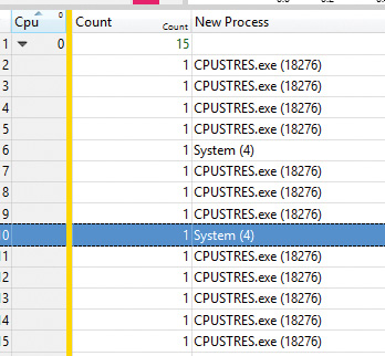
20. Notice in the CPU Usage (in View) (ms) column that the time spent in the System process is very small (micro seconds). Clearly, CPU 0 is dedicated to the CPUSTRES process.
21. Run CPUSET.exe with no arguments again. The first set (CPU 0) is marked Allocated: True because it’s now allocated to a particular process and not for general system use.
23. Enter the following command to restore the system CPU set to its default:
Cpuset -s 0
Thread selection on multiprocessor systems
Before covering multiprocessor systems in more detail, let’s summarize the algorithms discussed earlier in the “Thread selection” section. They either continued executing the current thread (if no new candidate was found) or started running the idle thread (if the current thread had to block). However, there is a third algorithm for thread selection called KiSearchForNewThread, which was hinted at earlier. This algorithm is called in one specific instance: when the current thread is about to block due to a wait on an object, including when doing an NtDelayExecutionThread call, also known as the Sleep API in Windows.
![]() Note
Note
This shows a subtle difference between the commonly used Sleep(1) call, which makes the current thread block until the next timer tick, and the SwitchToThread call, which was shown earlier. The Sleep(1) call uses the algorithm about to be described, while the SwitchToThread call uses the previously shown logic.
KiSearchForNewThread initially checks whether there is already a thread that was selected for this processor (by reading the NextThread field). If so, it dispatches this thread immediately in the running state. Otherwise, it calls the KiSelectReadyThreadEx routine and, if a thread was found, performs the same steps.
If no thread was found, the processor is marked as idle (even though the idle thread is not yet executing) and a scan of the queues of other logical processors (shared) is initiated (unlike the other standard algorithms, which would now give up). If, however, the processor core is parked, the algorithm will not attempt to check other logical processors, as it is preferable to allow the core to enter the parking state instead of keeping it busy with new work.
Barring these two scenarios, the work-stealing loop now runs. This code looks at the current NUMA node and removes any idle processors (because they shouldn’t have threads that need stealing). Then the code looks at the current CPU’s shared ready queue and calls KiSearchForNewThreadOnProcessor in a loop. If no thread is found, the affinity is changed to the next group and the function is called again. This time, however, the target CPU points it to the next group’s shared queue instead of the current one, causing this processor to find the best ready thread from the other processor group’s ready queue. If this fails to find a thread to run, local queues of processors in that group are searched in the same manner. If this is unsuccessful, and if DFSS is enabled, a thread from the idle-only queue of the remote logical processor is released on the current processor instead, if possible.
If no candidate ready thread is found, the next–lower numbered logical processor is attempted, and so on, until all logical processors have been exhausted on the current NUMA node. In this case, the algorithm keeps searching for the next-closest node, and so on, until all nodes in the current group have been exhausted. (Recall that Windows allows a given thread to have affinity only on a single group.) If this process fails to find any candidates, the function returns NULL and the processor enters the idle thread in the case of a wait (which will skip idle scheduling). If this work was already being done from the idle scheduler, the processor enters a sleep state.
Processor selection
We’ve described how Windows picks a thread when a logical processor needs to make a selection (or when a selection must be made for a given logical processor) and assumed the various scheduling routines have an existing database of ready threads to choose from. Now we’ll see how this database gets populated in the first place—in other words, how Windows chooses which LP’s ready queues to associate with a given ready thread. Having described the types of multiprocessor systems supported by Windows as well as thread-affinity and ideal processor settings, we’re now ready to examine how this information is used for this purpose.
Choosing a processor for a thread when there are idle processors
When a thread becomes ready to run, the KiDeferredReadyThread scheduler function is called. This prompts Windows to perform two tasks:
![]() Adjust priorities and refresh quantums as needed (as explained in the “Priority boosts” section).
Adjust priorities and refresh quantums as needed (as explained in the “Priority boosts” section).
![]() Pick the best logical processor for the thread.
Pick the best logical processor for the thread.
Windows first looks up the thread’s ideal processor and then it computes the set of idle processors within the thread’s hard affinity mask. This set is then pruned as follows:
1. Any idle logical processors that have been parked by the core-parking mechanism are removed. (See Chapter 6 for more information on core parking.) If this causes no idle processors to remain, idle processor selection is aborted, and the scheduler behaves as if no idle processors were available (described in the next section).
2. Any idle logical processors that are not on the ideal node (defined as the node containing the ideal processor) are removed (unless this would cause all idle processors to be eliminated).
3. On an SMT system, any non-idle SMT sets are removed, even if this might cause the elimination of the ideal processor itself. In other words, Windows prioritizes a non-ideal, idle SMT set over an ideal processor.
4. Windows checks whether the ideal processor is among the remaining set of idle processors. If not, it must then find the most appropriate idle processor. To do this, it first checks whether the processor that the thread last ran on is part of the remaining idle set. If so, it considers this processor to be a temporary ideal processor and selects it. (Recall that the ideal processor attempts to maximize processor cache hits, and picking the last processor a thread ran on is a good way of doing so.) If the last processor is not part of the remaining idle set, Windows checks whether the current processor (that is, the processor currently executing this scheduling code) is part of this set. If so, it applies the same logic as before.
5. If neither the last nor the current processor is idle, Windows performs one more pruning operation, removing any idle logical processors that are not on the same SMT set as the ideal processor. If there are none left, Windows instead removes any processors not on the SMT set of the current processor (unless this, too, eliminates all idle processors). In other words, Windows prefers idle processors that share the same SMT set as the unavailable ideal processor and/or last processor it would’ve liked to pick in the first place. Because SMT implementations share the cache on the core, this has nearly the same effect as picking the ideal or last processor from a caching perspective.
6. If after the previous step more than one processor remains in the idle set, Windows picks the lowest-numbered processor as the thread’s current processor.
After a processor has been selected for the thread to run on, that thread is put in the standby state and the idle processor’s PRCB is updated to point to this thread. If the processor is idle but not halted, a DPC interrupt is sent so that the processor handles the scheduling operation immediately. Whenever such a scheduling operation is initiated, KiCheckForThreadDispatch is called. It detects that a new thread has been scheduled on the processor and causes an immediate context switch if possible (as well as notifying Autoboost of the switch and delivering pending APCs). Alternatively, if no thread is pending, it causes a DPC interrupt to be sent.
Choosing a processor for a thread when there are no idle processors
If there are no idle processors when a thread wants to run, or if the only idle processors were eliminated by the first pruning (which got rid of parked idle processors), Windows first checks whether the latter situation has occurred. In this scenario, the scheduler calls KiSelectCandidateProcessor to ask the core-parking engine for the best candidate processor. The core-parking engine selects the highest-numbered processor that is unparked within the ideal node. If there are no such processors, the engine forcefully overrides the park state of the ideal processor and causes it to be unparked. Upon returning to the scheduler, it checks whether the candidate it received is idle; if so, it picks this processor for the thread, following the same last steps as in the previous scenario.
If this fails, Windows must decide whether to preempt the currently running thread. First, a target processor needs to be selected. The preference is in order of precedence: the ideal processor of the thread, the last processor the thread ran on, the first available processor in the current NUMA node, the closest processor on another NUMA node, and all these, barring affinity constraints, if any.
After a processor is selected, the next question is whether the new thread should preempt the current one on that processor. This is done by comparing the ranks of the two threads. This is an internal scheduling number that indicates the relative power of a thread based on its scheduling group and other factors. (See the section “Group-based scheduling” later in this chapter for a detailed discussion of group scheduling and rank.) If the rank of the new thread is zero (highest) or lower than the current thread’s rank, or the ranks are equal but the priority of the new thread is higher than the currently executing one, then preemption should occur. The currently running thread is marked to be preempted, and Windows queues a DPC interrupt to the target processor to preempt the currently running thread in favor of this new thread.
If the ready thread cannot be run right away, it is moved into the ready state on the shared or local queue (as appropriate based on affinity constraints), where it will await its turn to run. As seen in the scheduling scenarios earlier, the thread will be inserted either at the head or the tail of the queue, based on whether it entered the ready state due to preemption.
![]() Note
Note
Regardless of the underlying scenario and various possibilities, threads are mostly put on their ideal processor’s per-processor ready queues, guaranteeing the consistency of the algorithms that determine how a logical processor picks a thread to run.
Heterogeneous scheduling (big.LITTLE)
The kernel assumes an SMP system, as previously described. However, some ARM-based processors contain multiple cores that are not the same. A typical ARM CPU (for example, from Qualcomm) contains some powerful cores, which should run for short periods at a time (and consume more energy), and a set of weaker cores, which can run for longer periods (and consume less energy). This is sometimes called big.LITTLE.
Windows 10 introduced the ability to distinguish between these cores and schedule threads based on the core’s size and policy, including the foreground status of the thread, its priority, and its expected run time. Windows initializes the set of processors when the Power Manager is initialized by calling PopInitializeHeteroProcessors (and if processors are hot-added to the system). The function allows the simulation of hetero systems (for example, for testing purposes) by adding keys under the registry key HKLM\System\CurrentControlSet\Control\Session Manager\Kernel\KGroups as follows:
![]() A key should use two decimal digits to identify a processor group number. (Recall that each group holds at most 64 processors.) For example, 00 is the first group, 01 is the second, etc. (On most systems, one group would suffice.)
A key should use two decimal digits to identify a processor group number. (Recall that each group holds at most 64 processors.) For example, 00 is the first group, 01 is the second, etc. (On most systems, one group would suffice.)
![]() Each key should contain a
Each key should contain a DWORD value named SmallProcessorMask that is a mask of processors that would be considered small. For example, if the value is 3 (the first two bits are on) and the group has six total processors, that would mean processors 0 and 1 (3 = 1 or 2) are small, while the other four processors are big. This is essentially the same as an affinity mask.
The kernel has several policy options that can be tweaked when dealing with hetero systems, stored in global variables. Table 4-5 shows some of these variables and their meaning.
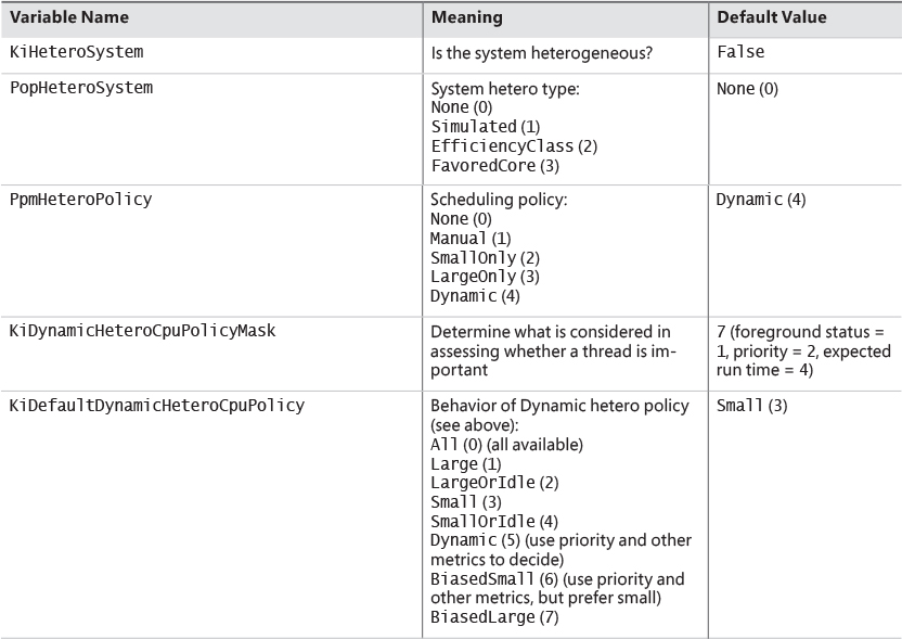
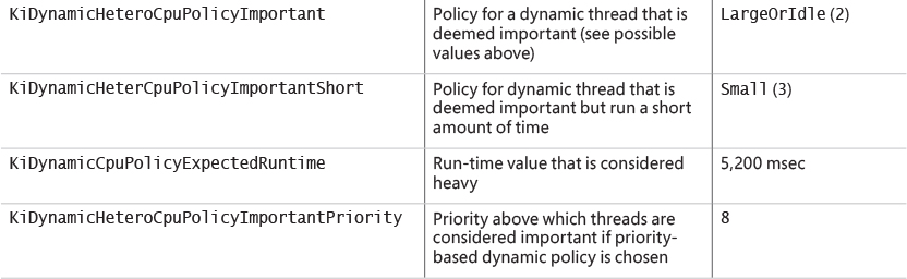
Dynamic policies (refer to Table 4-5) must be translated to an importance value based on KiDynamic- HeteroPolicyMask and the thread’s state. This is done by the KiConvertDynamicHeteroPolicy function, which checks, in order, the foreground state of the thread, its priority relative to KiDynamic-HeteroCpuPolicyImportantPriority, and its expected run time. If the thread is deemed important (if running time is the determining factor, then it could be short as well), the important-related policy is used for scheduling decisions. (In Table 4-5, this would be KiDynamicHeteroCpuPolicyImportant-Short or KiDynamicHeteroCpuPolicyImportant.)
Group-based scheduling
The previous section described the standard thread-based scheduling implementation of Windows. Since its appearance in the first release of Windows NT (with scalability improvements done with each subsequent release), it has reliably served general user and server scenarios. However, because thread-based scheduling attempts to fairly share the processor or processors only among competing threads of the same priority, it does not account for higher-level requirements such as the distribution of threads to users and the potential for certain users to benefit from more overall CPU time at the expense of other users. This is problematic in terminal-services environments, in which dozens of users compete for CPU time. If only thread-based scheduling is used, a single high-priority thread from a given user has the potential to starve threads from all users on the machine.
Windows 8 and Server 2012 introduced a group-based scheduling mechanism, built around the concept of a scheduling group (KSCHEDULING_GROUP). A scheduling group maintains a policy, scheduling parameters (described shortly), and a list of kernel scheduling control blocks (KSCBs), one per processor, that are part of the scheduling group. The flip side is that a thread points to a scheduling group it belongs to. If that pointer is null, it means the thread is outside any scheduling group’s control. Figure 4-19 shows the structure of a scheduling group. In this figure, threads T1, T2, and T3 belong to the scheduling group, while thread T4 does not.
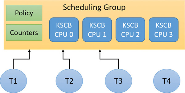
Here are some terms related to group scheduling:
![]() Generation This is the amount of time over which to track CPU usage.
Generation This is the amount of time over which to track CPU usage.
![]() Quota This is the amount of CPU usage allowed to a group per generation. Over quota means the group has used up all its budget. Under quota means the group has not used its full budget.
Quota This is the amount of CPU usage allowed to a group per generation. Over quota means the group has used up all its budget. Under quota means the group has not used its full budget.
![]() Weight This is the relative importance of a group, between 1 and 9, where the default is 5.
Weight This is the relative importance of a group, between 1 and 9, where the default is 5.
![]() Fair-share scheduling With this type of scheduling, idle cycles can be given to threads that are over quota if no under-quota threads want to run.
Fair-share scheduling With this type of scheduling, idle cycles can be given to threads that are over quota if no under-quota threads want to run.
The KSCB structure contains CPU-related information as follows:
![]() Cycle usage for this generation
Cycle usage for this generation
![]() Long-term average cycle usage, so that a burst of thread activity can be distinguished from a true hog
Long-term average cycle usage, so that a burst of thread activity can be distinguished from a true hog
![]() Control flags such as hard capping, which means that even if CPU time is available above the assigned quota, it will not be used to give the thread extra CPU time
Control flags such as hard capping, which means that even if CPU time is available above the assigned quota, it will not be used to give the thread extra CPU time
![]() Ready queues, based on the standard priorities (0 to 15 only because real-time threads are never part of a scheduling group)
Ready queues, based on the standard priorities (0 to 15 only because real-time threads are never part of a scheduling group)
An important parameter maintained by a scheduling group is called rank, which can be considered a scheduling priority of the entire group of threads. A rank with a value of 0 is the highest. A higher-rank number means the group has used more CPU time and so is less likely to get more CPU time. Rank always trumps priority. This means that given two threads with different ranks, the lower value rank is preferred, regardless of priority. Equal-rank threads are compared based on priority. The rank is adjusted periodically as cycle usage increases.
Rank 0 is the highest (so it always wins out) against a higher number rank, and is implicit for some threads. This can indicate one of the following:
![]() The thread is not in any scheduling group (“normal” threads)
The thread is not in any scheduling group (“normal” threads)
![]() Under-quota threads
Under-quota threads
![]() Real-time priority threads (16–31)
Real-time priority threads (16–31)
![]() Threads executing at
Threads executing at IRQL APC_LEVEL (1) within a kernel critical or guarded region (see Chapter 8 in Part 2 for more on APCs and regions)
At various scheduling choices (for example, KiQuantumEnd), the decision of which thread to schedule next accounts for the scheduling group (if any) of the current and ready threads. If a scheduling group exists, the lowest value rank wins out, followed by priority (if ranks are equal), followed by the first arriving thread (if priorities are equal; round-robin at quantum end).
Dynamic fair share scheduling
Dynamic fair share scheduling (DFSS) is a mechanism that can be used to fairly distribute CPU time among sessions running on a machine. It prevents one session from potentially monopolizing the CPU if some threads running under that session have a relatively high priority and run a lot. It’s enabled by default on a Windows Server system that has the Remote Desktop role. However, it can be configured on any system, client or server. Its implementation is based on group scheduling described in the previous section.
During the very last parts of system initialization, as the registry SOFTWARE hive is initialized by Smss.exe, the process manager initiates the final post-boot initialization in PsBootPhaseComplete, which calls PspIsDfssEnabled. Here, the system decides which of the two CPU quota mechanisms (DFSS or legacy) will be employed. For DFSS to be enabled, the EnableCpuQuota registry value must be set to a non-zero value in both of the quota keys. The first of these is HKLM\SOFTWARE\Policies\Microsoft\Windows\Session Manager\Quota System, for the policy-based setting. The second is HKLM\SYSTEM\CurrentControlSet\Control\Session Manager\Quota System, under the system key. This determines whether the system supports the functionality (which, by default, is set to TRUE on Windows Server with the Remote Desktop role).
If DFSS is enabled, the PsCpuFairShareEnabled global variable is set to TRUE, which makes all threads belong to scheduling groups (except session 0 processes). DFSS configuration parameters are read from the aforementioned keys by a call to PspReadDfssConfigurationValues and stored in global variables. These keys are monitored by the system. If modified, the notification callback calls PspReadDfssConfigurationValues again to update the configuration values. Table 4-6 shows the values and their meaning.
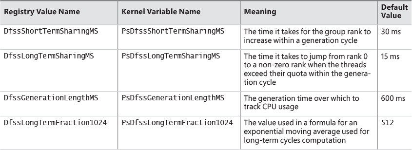
After DFSS is enabled, whenever a new session is created (other than session 0), MiSessionObjectCreate allocates a scheduling group associated with the session with the default weight of 5, which is the middle ground between the minimum of 1 and the maximum of 9. A scheduling group manages either DFSS or CPU rate-control (see the next section) information based on a policy structure (KSCHEDULING_GROUP_POLICY) that is part of a scheduling group. The Type member indicates whether it’s configured for DFSS (WeightBased=0) or rate control (RateControl=1). MiSessionObjectCreate calls KeInsertSchedulingGroup to insert the scheduling group into a global system list (maintained in the global variable KiSchedulingGroupList, needed for weight recalculation if processors are hot-added). The resulting scheduling group is also pointed to by the SESSION_OBJECT structure for the particular session.
1. Add the registry keys and values as described in this section to enable DFSS on the system. (You can try this experiment on a VM as well.) Then restart the system for the changes to take effect.
2. To make sure DFSS is active, open a live kernel debug session and inspect the value of PsCpuFairShareEnabled by issuing the following command. A value of 1 indicates DFSS is active.
lkd> db nt!PsCpuFairShareEnabled L1
fffff800'5183722a 01
3. In the debugger, look at the current thread. (It should be one of the threads running WinDbg.) Notice that the thread is part of a scheduling group and that its KSCB is not NULL because the thread was running at the time of display.
lkd> !thread
THREAD ffffd28c07231640 Cid 196c.1a60 Teb: 000000f897f4b000 Win32Thread:
ffffd28c0b9b0b40 RUNNING on processor 1
IRP List:
ffffd28c06dfac10: (0006,0118) Flags: 00060000 Mdl: 00000000
Not impersonating
DeviceMap ffffac0d33668340
Owning Process ffffd28c071fd080 Image: windbg.exe
Attached Process N/A Image: N/A
Wait Start TickCount 6146 Ticks: 33 (0:00:00:00.515)
Context Switch Count 877 IdealProcessor: 0
UserTime 00:00:00.468
KernelTime 00:00:00.156
Win32 Start Address 0x00007ff6ac53bc60
Stack Init ffffbf81ae85fc90 Current ffffbf81ae85f980
Base ffffbf81ae860000 Limit ffffbf81ae85a000 Call 0000000000000000
Priority 8 BasePriority 8 PriorityDecrement 0 IoPriority 2 PagePriority 5
Scheduling Group: ffffd28c089e7a40 KSCB: ffffd28c089e7c68 rank 0
4. Enter the dt command to view the scheduling group:
lkd> dt nt!_kscheduling_group ffffd28c089e7a40
+0x000 Policy : _KSCHEDULING_GROUP_POLICY
+0x008 RelativeWeight : 0x80
+0x00c ChildMinRate : 0x2710
+0x010 ChildMinWeight : 0
+0x014 ChildTotalWeight : 0
+0x018 QueryHistoryTimeStamp : 0xfed6177
+0x020 NotificationCycles : 0n0
+0x028 MaxQuotaLimitCycles : 0n0
+0x030 MaxQuotaCyclesRemaining : 0n-73125382369
+0x038 SchedulingGroupList : _LIST_ENTRY [ 0xfffff800'5179b110 -
0xffffd28c'081b7078 ]
+0x038 Sibling : _LIST_ENTRY [ 0xfffff800'5179b110 -
0xffffd28c'081b7078 ]
+0x048 NotificationDpc : 0x0002eaa8'0000008e _KDPC
+0x050 ChildList : _LIST_ENTRY [ 0xffffd28c'062a7ab8 -
0xffffd28c'05c0bab8 ]
+0x060 Parent : (null)
+0x080 PerProcessor : [1] _KSCB
5. Create another local user on the machine.
6. Run CPU Stress in the current session.
7. Make a few threads run at maximum activity, but not enough to overwhelm the machine. For example, the following image shows two threads running at maximum activity on a three-processor virtual machine:
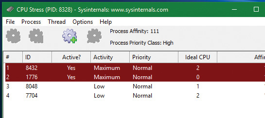
8. Press Ctrl+Alt+Del and select Switch User. Then select and log in to the account for the other user you created.
9. Run CPU Stress again, making the same number of threads run with maximum activity.
10. For the CPUSTRES process, open the Process menu, choose Priority Class, and select High to change the process priority class. Without DFSS, that higher-priority process should consume most of the CPU. This is because there are four threads competing for three processors. One of these will lose out, and it should be from the lower-priority process.
11. Open Process Explorer, double-click both CPUSTRES processes, and select the Performance Graph tab.
12. Place both windows side by side. You should see the CPU consumed roughly evenly between the processes, even though their priorities are not the same:
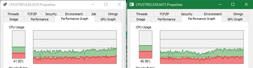
13. Disable DFSS by removing the registry keys. Then restart the system.
14. Rerun the experiment. You should clearly see the difference with the higher-priority process receiving the most CPU time.
CPU rate limits
DFSS works by automatically placing new threads inside the session-scheduling group. This is fine for a terminal-services scenario, but is not good enough as a general mechanism to limit the CPU time of threads or processes.
The scheduling-group infrastructure can be used in a more granular fashion by using a job object. Recall from Chapter 3 that a job can manage one or more processes. One of the limitations you can place on a job is a CPU rate control, which you do by calling SetInformationJobObject with Job-ObjectCpuRateControlInformation as the job information class and a structure of type JOBOBJECT_CPU_RATE_CONTROL_INFORMATION containing the actual control data. The structure contains a set of flags that enable you to apply one of three settings to limit CPU time:
![]() CPU rate This value can be between 1 and 10000 and represents a percent multiplied by 100 (for example, for 40 percent the value should be 4000).
CPU rate This value can be between 1 and 10000 and represents a percent multiplied by 100 (for example, for 40 percent the value should be 4000).
![]() Weight-based This value can be between 1 and 9, relative to the weight of other jobs. (DFSS is configured with this setting.)
Weight-based This value can be between 1 and 9, relative to the weight of other jobs. (DFSS is configured with this setting.)
![]() Minimum and maximum CPU rates These values are specified similarly to the first option. When the threads in the job reach the maximum percentage specified in the measuring interval (600 ms by default), they cannot get any more CPU time until the next interval begins. You can use a control flag to specify whether to use hard capping to enforce the limit even if there is spare CPU time available.
Minimum and maximum CPU rates These values are specified similarly to the first option. When the threads in the job reach the maximum percentage specified in the measuring interval (600 ms by default), they cannot get any more CPU time until the next interval begins. You can use a control flag to specify whether to use hard capping to enforce the limit even if there is spare CPU time available.
The net result of setting these limits is to place all threads from all processes that are in the job in a new scheduling group and configuring the group as specified.
1. Run CPU Stress on the test VM and configure a few threads to consume about 50 percent of CPU time. For example, on an eight-processor system, activate four threads that run with maximum activity level:
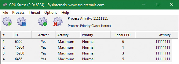
2. Open Process Explorer, find the CPUSTRES instance, open its properties, and select the Performance Graph tab. The CPU usage should be roughly 50 percent.
3. Download the CPULIMIT tool from the book’s downloadable resources. This is a simple tool that allows you to limit the CPU usage of a single process through hard capping.
4. Run the command shown to limit the CPU usage to 20 percent for the CPUSTRES process. (Replace the number 6324 with your process ID.)
CpuLimit.exe 6324 20
5. Look at the Process Explorer window. You should see the drop to around 20 percent:
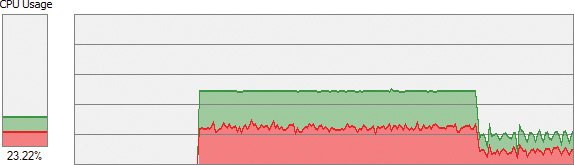
6. Open WinDbg on the host system.
7. Attach to the kernel of the test system and break into it.
8. Enter the following command to locate the CPUSTRES process:
0: kd> !process 0 0 cpustres.exe
PROCESS ffff9e0629528080
SessionId: 1 Cid: 18b4 Peb: 009e4000 ParentCid: 1c4c
DirBase: 230803000 ObjectTable: ffffd78d1af6c540 HandleCount: <Data
Not Accessible>
Image: CPUSTRES.exe
9. Type the following command to list basic information for the process:
0: kd> !process ffff9e0629528080 1
PROCESS ffff9e0629528080
SessionId: 1 Cid: 18b4 Peb: 009e4000 ParentCid: 1c4c
DirBase: 230803000 ObjectTable: ffffd78d1af6c540 HandleCount: <Data
Not Accessible>
Image: CPUSTRES.exe
VadRoot ffff9e0626582010 Vads 88 Clone 0 Private 450. Modified 4. Locked 0.
DeviceMap ffffd78cd8941640
Token ffffd78cfe3db050
ElapsedTime 00:08:38.438
UserTime 00:00:00.000
KernelTime 00:00:00.000
QuotaPoolUsage[PagedPool] 209912
QuotaPoolUsage[NonPagedPool] 11880
Working Set Sizes (now,min,max) (3296, 50, 345) (13184KB, 200KB, 1380KB)
PeakWorkingSetSize 3325
VirtualSize 108 Mb
PeakVirtualSize 128 Mb
PageFaultCount 3670
MemoryPriority BACKGROUND
BasePriority 8
CommitCharge 568
Job ffff9e06286539a0
10. Notice there is a non-NULL job object. Show its properties with the !job command. The tool creates a job (CreateJobObject), adds the process to the job (AssignProcessToJobObject), and calls SetInformationJobObject with the CPU rate information class and rate value of 2000 (20 percent).
0: kd> !job ffff9e06286539a0
Job at ffff9e06286539a0
Basic Accounting Information
TotalUserTime: 0x0
TotalKernelTime: 0x0
TotalCycleTime: 0x0
ThisPeriodTotalUserTime: 0x0
ThisPeriodTotalKernelTime: 0x0
TotalPageFaultCount: 0x0
TotalProcesses: 0x1
ActiveProcesses: 0x1
FreezeCount: 0
BackgroundCount: 0
TotalTerminatedProcesses: 0x0
PeakJobMemoryUsed: 0x248
PeakProcessMemoryUsed: 0x248
Job Flags
[close done]
[cpu rate control]
Limit Information (LimitFlags: 0x0)
Limit Information (EffectiveLimitFlags: 0x800)
CPU Rate Control
Rate = 20.00%
Hard Resource Cap
Scheduling Group: ffff9e0628d7c1c0
11. Rerun the CPULIMIT tool on the same process and again set the CPU rate to 20 percent. You should see the CPU consumption of CPUSTRES drop down to around 4 percent. This is because of job nesting. A new job is created, as is the process assigned to it, nested under the first job. The net result is 20 percent of 20 percent, which is 4 percent.
Dynamic processor addition and replacement
As you’ve seen, developers can fine-tune which threads are allowed to (and in the case of the ideal processor, should) run on which processor. This works fine on systems that have a constant number of processors during their run time. For example, desktop machines require shutting down the computer to make any sort of hardware changes to the processor or their count. Today’s server systems, however, cannot afford the downtime that CPU replacement or addition normally requires. In fact, you may be required to add a CPU at times of high load that is above what the machine can support at its current level of performance. Having to shut down the server during a period of peak usage would defeat the purpose.
To address this requirement, the latest generation of server motherboards and systems support the addition of processors (as well as their replacement) while the machine is still running. The ACPI BIOS and related hardware on the machine have been specifically built to allow and be aware of this need, but OS participation is required for full support.
Dynamic processor support is provided through the HAL, which notifies the kernel of a new processor on the system through the KeStartDynamicProcessor function. This routine does similar work to that performed when the system detects more than one processor at startup and needs to initialize the structures related to them. When a dynamic processor is added, various system components perform some additional work. For example, the memory manager allocates new pages and memory structures optimized for the CPU. It also initializes a new DPC kernel stack while the kernel initializes the global descriptor table (GDT), the interrupt dispatch table (IDT), the processor control region (PCR), the process control block (PRCB), and other related structures for the processor.
Other executive parts of the kernel are also called, mostly to initialize the per-processor look-aside lists for the processor that was added. For example, the I/O manager, executive look-aside list code, cache manager, and object manager all use per-processor look-aside lists for their frequently allocated structures.
Finally, the kernel initializes threaded DPC support for the processor and adjusts exported kernel variables to report the new processor. Different memory-manager masks and process seeds based on processor counts are also updated, and processor features need to be updated for the new processor to match the rest of the system—for example, enabling virtualization support on the newly added processor. The initialization sequence completes with the notification to the Windows Hardware Error Architecture (WHEA) component that a new processor is online.
The HAL is also involved in this process. It is called once to start the dynamic processor after the kernel is aware of it, and called again after the kernel has finished initialization of the processor. However, these notifications and callbacks only make the kernel aware and respond to processor changes. Although an additional processor increases the throughput of the kernel, it does nothing to help drivers.
To handle drivers, the system has a default executive callback object, ProcessorAdd, with which drivers can register for notifications. Similar to the callbacks that notify drivers of power state or system time changes, this callback allows driver code to, for example, create a new worker thread if desirable so that it can handle more work at the same time.
Once drivers are notified, the final kernel component called is the Plug and Play manager, which adds the processor to the system’s device node and rebalances interrupts so that the new processor can handle interrupts that were already registered for other processors. CPU-hungry applications are also able to take advantage of the new processors.
However, a sudden change of affinity can have potentially breaking changes for a running application—especially when going from a single-processor to a multiprocessor environment—through the appearance of potential race conditions or simply misdistribution of work (because the process might have calculated the perfect ratios at startup, based on the number of CPUs it was aware of). As a result, applications do not take advantage of a dynamically added processor by default. They must request it.
The SetProcessAffinityUpdateMode and QueryProcessAffinityUpdateMode Windows APIs, which use the undocumented NtSet/QueryInformationProcess system call) tell the process manager that these applications should have their affinity updated (by setting the AffinityUpdateEnable flag in EPROCESS) or that they do not want to deal with affinity updates (by setting the AffinityPermanent flag in EPROCESS). This is a one-time change. After an application has told the system that its affinity is permanent, it cannot later change its mind and request affinity updates.
As part of KeStartDynamicProcessor, a new step has been added after interrupts are rebalanced: calling the process manager to perform affinity updates through PsUpdateActiveProcessAffinity. Some Windows core processes and services already have affinity updates enabled, while third-party software will need to be recompiled to take advantage of the new API call. The System process, Svchost processes, and Smss are all compatible with dynamic processor addition.
Worker factories (thread pools)
Worker factories are the internal mechanism used to implement user-mode thread pools. The legacy thread-pool routines were completely implemented in user mode inside the Ntdll.dll library. In addition, the Windows API provided several functions for developers to call, which provided waitable timers (CreateTimerQueue, CreateTimerQueueTimer, and friends), wait callbacks (RegisterWaitForSingleObject), and work item processing with automatic thread creation and deletion (QueueUserWorkItem), depending on the amount of work being done.
One issue with the old implementation was that only one thread pool could be created in a process, which made some scenarios difficult to implement. For example, trying to prioritize work items by building two thread pools which would serve a different set of requests was not directly possible. The other issue was the implementation itself, which was in user mode (in Ntdll.dll). Because the kernel can have direct control over thread scheduling, creation, and termination without the typical costs associated with doing these operations from user mode, most of the functionality required to support the user-mode thread pool implementation in Windows is now located in the kernel. This also simplifies the code that developers need to write. For example, creating a worker pool in a remote process can be done with a single API call instead of the complex series of virtual memory calls this normally requires. Under this model, Ntdll.dll merely provides the interfaces and high-level APIs required for interfacing with the worker factory kernel code.
This kernel thread pool functionality in Windows is managed by an object manager type called TpWorkerFactory, as well as four native system calls for managing the factory and its workers (NtCreateWorkerFactory, NtWorkerFactoryWorkerReady, NtReleaseWorkerFactoryWorker, and NtShutdownWorkerFactory); two query/set native calls (NtQueryInformationWorkerFactory and NtSetInformationWorkerFactory); and a wait call (NtWaitForWorkViaWorkerFactory). Just like other native system calls, these calls provide user mode with a handle to the TpWorkerFactory object, which contains information such as the name and object attributes, the desired access mask, and a security descriptor. Unlike other system calls wrapped by the Windows API, however, thread-pool management is handled by Ntdll.dll’s native code. This means developers work with opaque descriptors: a TP_POOL pointer for a thread pool and other opaque pointers for object created from a pool, including TP_WORK (work callback), TP_TIMER (timer callback), TP_WAIT (wait callbacks), etc. These structures hold various pieces of information, such as the handle to the TpWorkerFactory object.
As its name suggests, the worker factory implementation is responsible for allocating worker threads (and calling the given user-mode worker thread entry point) and maintaining a minimum and maximum thread count (allowing for either permanent worker pools or totally dynamic pools) as well as other accounting information. This enables operations such as shutting down the thread pool to be performed with a single call to the kernel because the kernel has been the only component responsible for thread creation and termination.
Because the kernel dynamically creates new threads as needed (based on minimum and maximum numbers provided), this increases the scalability of applications using the new thread-pool implementation. A worker factory will create a new thread whenever all of the following conditions are met:
![]() Dynamic thread creation is enabled.
Dynamic thread creation is enabled.
![]() The number of available workers is lower than the maximum number of workers configured for the factory (default of 500).
The number of available workers is lower than the maximum number of workers configured for the factory (default of 500).
![]() The worker factory has bound objects (for example, an ALPC port that this worker thread is waiting on) or a thread has been activated into the pool.
The worker factory has bound objects (for example, an ALPC port that this worker thread is waiting on) or a thread has been activated into the pool.
![]() There are pending I/O request packets (IRPs; see Chapter 6 for more information) associated with a worker thread.
There are pending I/O request packets (IRPs; see Chapter 6 for more information) associated with a worker thread.
In addition, it will terminate threads whenever they’ve become idle—that is, they haven’t processed any work item—for more than 10 seconds (by default). Furthermore, although developers have always been able to take advantage of as many threads as possible (based on the number of processors on the system) through the old implementation, it’s now possible for applications using thread pools to automatically take advantage of new processors added at run time. This is through its support for dynamic processors in Windows Server (as discussed earlier in this chapter).
Worker factory creation
The worker factory support is merely a wrapper to manage mundane tasks that would otherwise have to be performed in user mode (at a loss of performance). Much of the logic of the new thread-pool code remains in the Ntdll.dll side of this architecture. (Theoretically, by using undocumented functions, a different thread-pool implementation can be built around worker factories.) Also, it is not the worker factory code that provides the scalability, wait internals, and efficiency of work processing. Instead, it is a much older component of Windows: I/O completion ports or, more correctly, kernel queues (KQUEUE). In fact, when creating a worker factory, an I/O completion port must have already been created by user mode, and the handle needs to be passed in.
It is through this I/O completion port that the user-mode implementation will queue and wait for work—but by calling the worker factory system calls instead of the I/O completion port APIs. Internally, however, the “release” worker factory call (which queues work) is a wrapper around IoSetIoCompletionEx, which increases pending work, while the “wait” call is a wrapper around IoRemoveIoCompletion. Both these routines call into the kernel queue implementation. Therefore, the job of the worker factory code is to manage either a persistent, static, or dynamic thread pool; wrap the I/O completion port model into interfaces that try to prevent stalled worker queues by automatically creating dynamic threads; and simplify global cleanup and termination operations during a factory shutdown request (as well as easily block new requests against the factory in such a scenario).
The executive function that creates the worker factory, NtCreateWorkerFactory, accepts several arguments that allow customization of the thread pool, such as the maximum threads to create and the initial committed and reserved stack sizes. The CreateThreadpool Windows API, however, uses the default stack sizes embedded in the executable image (just like a default CreateThread would). The Windows API does not, however, provide a way to override these defaults. This is somewhat unfortunate, as in many cases thread-pool threads don’t require deep call stacks, and it would be beneficial to allocate smaller stacks.
The data structures used by the worker factory implementation are not in the public symbols, but it is still possible to look at some worker pools, as you’ll see in the next experiment. Additionally, the NtQueryInformationWorkerFactory API dumps almost every field in the worker factory structure.
EXPERIMENT: Looking at thread pools
1. Run Process Explorer.
2. Open the View menu and select Show Unnamed Handles and Mappings. (Unfortunately, worker factories aren’t named by Ntdll.dll, so you need to take this step to see the handles.)
3. Select an instance of svchost.exe from the list of processes.
4. Open the View menu and choose Show Lower Pane to display the lower pane of the handle table.
5. Open the View menu, choose Lower Pane View, and select Handles to display the table in handle mode.
6. Right-click the lower pane column headers and choose Select Columns.
7. Make sure the Type and Handle Value columns are checked.
8. Click the Type header to sort by type.
9. Scroll down the handles, looking at the Type column, until you find a handle of type TpWorkerFactory.
10. Click the Handle header to sort by handle value. You should see something similar to the following screenshot. Notice how the TpWorkerFactory handle is immediately preceded by an IoCompletion handle. As discussed, this occurs because a handle to an I/O completion port on which work will be sent must be created before creating a worker factory.
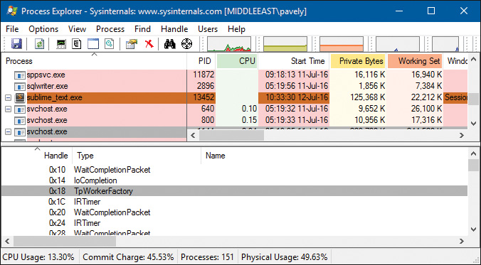
11. Double-click the selected process in the list of processes, click the Threads tab, and click the Start Address column. You should see something similar to the following screenshot. Worker factory threads are easily identified by their Ntdll.dll’s entry point, TppWorkerThread. (Tpp stands for thread pool private.)
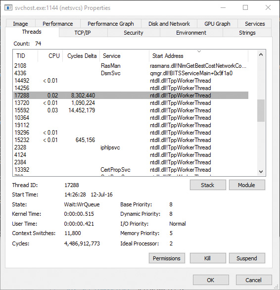
If you look at other worker threads, you’ll see some are waiting for objects such as events. A process can have multiple thread pools, and each thread pool can have a variety of threads doing completely unrelated tasks. It’s up to the developer to assign work and to call the thread-pool APIs to register this work through Ntdll.dll.
Conclusion
This chapter examined the structure of threads, how they are created and managed, and how Windows decides which threads should run, for how long, and on which processor or processors. In the next chapter, you’ll look at one of the most important aspects of any OS: memory management.


Comments
Post a Comment