Chapter 5. Memory management
Chapter 5. Memory management
In this chapter, you’ll learn how Windows implements virtual memory and how it manages the subset of virtual memory kept in physical memory. We’ll also describe the internal structure and components that make up the memory manager, including key data structures and algorithms. Before examining these mechanisms, we’ll review the basic services provided by the memory manager and key concepts such as reserved memory versus committed memory and shared memory.
Introduction to the memory manager
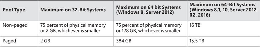
By default, the virtual size of a process on 32-bit Windows is 2 GB. If the image is marked specifically as large address space–aware, and the system is booted with a special option (described in the section “x86 address space layouts” later in this chapter), a 32-bit process can grow to be up to 3 GB on 32-bit Windows and to 4 GB on 64-bit Windows. The process virtual address space size on 64-bit Windows 8 and Server 2012 is 8192 GB (8 TB) and on 64 bit Windows 8.1 (and later) and Server 2012 R2 (and later), it is 128 TB.
As you saw in Chapter 2, “System architecture”—specifically in Table 2-2—the maximum amount of physical memory currently supported by Windows ranges from 2 GB to 24 TB, depending on which version and edition of Windows you are running. Because the virtual address space might be larger or smaller than the physical memory on the machine, the memory manager has two primary tasks:
![]() Translating, or mapping, a process’s virtual address space into physical memory so that when a thread running in the context of that process reads or writes to the virtual address space, the correct physical address is referenced. (The subset of a process’s virtual address space that is physically resident is called the working set. Working sets are described in more detail in the section “Working sets” later in this chapter.)
Translating, or mapping, a process’s virtual address space into physical memory so that when a thread running in the context of that process reads or writes to the virtual address space, the correct physical address is referenced. (The subset of a process’s virtual address space that is physically resident is called the working set. Working sets are described in more detail in the section “Working sets” later in this chapter.)
![]() Paging some of the contents of memory to disk when it becomes overcommitted—that is, when running threads try to use more physical memory than is currently available—and bringing the contents back into physical memory when needed.
Paging some of the contents of memory to disk when it becomes overcommitted—that is, when running threads try to use more physical memory than is currently available—and bringing the contents back into physical memory when needed.
In addition to providing virtual memory management, the memory manager provides a core set of services on which the various Windows environment subsystems are built. These services include memory-mapped files (internally called section objects), copy-on-write memory, and support for applications using large, sparse address spaces. The memory manager also provides a way for a process to allocate and use larger amounts of physical memory than can be mapped into the process virtual address space at one time—for example, on 32-bit systems with more than 3 GB of physical memory. This is explained in the section “Address Windowing Extensions” later in this chapter.
There is a Control Panel applet (System) that provides control over the size, number, and locations of paging files. Its nomenclature suggests that virtual memory is the same thing as the paging file. This is not the case. The paging file is only one aspect of virtual memory. In fact, even if you run with no page file at all, Windows will still be using virtual memory. This distinction is explained in more detail later in this chapter.
Memory manager components
The memory manager is part of the Windows executive and therefore exists in the file Ntoskrnl.exe. It’s the largest component in the executive, hinting at its importance and complexity. No parts of the memory manager exist in the HAL. The memory manager consists of the following components:
![]() A set of executive system services for allocating, deallocating, and managing virtual memory, most of which are exposed through the Windows API or kernel-mode device driver interfaces
A set of executive system services for allocating, deallocating, and managing virtual memory, most of which are exposed through the Windows API or kernel-mode device driver interfaces
![]() A translation-not-valid and access fault trap handler for resolving hardware-detected memory-management exceptions and making virtual pages resident on behalf of a process
A translation-not-valid and access fault trap handler for resolving hardware-detected memory-management exceptions and making virtual pages resident on behalf of a process
![]() Six key top-level routines, each running in one of six different kernel-mode threads in the System process:
Six key top-level routines, each running in one of six different kernel-mode threads in the System process:
• The balance set manager (KeBalanceSetManager, priority 17) This calls an inner routine, the working set manager (MmWorkingSetManager), once per second as well as when free memory falls below a certain threshold. The working set manager drives the overall memory-management policies, such as working set trimming, aging, and modified page writing.
• The process/stack swapper (KeSwapProcessOrStack, priority 23) This performs both process and kernel thread stack inswapping and outswapping. The balance set manager and the thread-scheduling code in the kernel awaken this thread when an inswap or outswap operation needs to take place.
• The modified page writer (MiModifiedPageWriter, priority 18) This writes dirty pages on the modified list back to the appropriate paging files. This thread is awakened when the size of the modified list needs to be reduced.
• The mapped page writer (MiMappedPageWriter, priority 18) This writes dirty pages in mapped files to disk or remote storage. It is awakened when the size of the modified list needs to be reduced or if pages for mapped files have been on the modified list for more than 5 minutes. This second modified page writer thread is necessary because it can generate page faults that result in requests for free pages. If there were no free pages and only one modified page writer thread, the system could deadlock waiting for free pages.
• The segment dereference thread (MiDereferenceSegmentThread, priority 19) This is responsible for cache reduction as well as for page file growth and shrinkage. For example, if there is no virtual address space for paged pool growth, this thread trims the page cache so that the paged pool used to anchor it can be freed for reuse.
• The zero page thread (MiZeroPageThread, priority 0) This zeroes out pages on the free list so that a cache of zero pages is available to satisfy future demand-zero page faults. In some cases, memory zeroing is done by a faster function called MiZeroInParallel. See the note in the “Page list dynamics” section later in this chapter.
Each of these components is covered in more detail later in the chapter except for the segment dereference thread, which is covered in Chapter 14, “Cache manager,” in Part 2.
Large and small pages
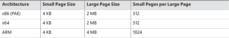
Memory management is done in distinct chunks called pages. This is because the hardware memory management unit translates virtual to physical addresses at the granularity of a page. Hence, a page is the smallest unit of protection at the hardware level. (The various page-protection options are described in the section “Protecting memory” later in this chapter.) The processors on which Windows runs support two page sizes: small and large. The actual sizes vary based on the processor architecture, and they are listed in Table 5-1.
![]() Note
Note
Some processors support configurable page sizes, but Windows does not use this feature.
The primary advantage of large pages is speed of address translation for references to data within the large page. This advantage exists because the first reference to any byte within a large page will cause the hardware’s translation look-aside buffer (TLB) (described in the section “Address translation” later in this chapter), to have in its cache the information necessary to translate references to any other byte within the large page. If small pages are used, more TLB entries are needed for the same range of virtual addresses, thus increasing the recycling of entries as new virtual addresses require translation. This, in turn, means having to go back to the page table structures when references are made to virtual addresses outside the scope of a small page whose translation has been cached. The TLB is a very small cache; thus, large pages make better use of this limited resource.
To take advantage of large pages on systems with more than 2 GB of RAM, Windows maps with large pages the core operating system images (Ntoskrnl.exe and Hal.dll) as well as core operating system data (such as the initial part of non-paged pool and the data structures that describe the state of each physical memory page). Windows also automatically maps I/O space requests (calls by device drivers to MmMapIoSpace) with large pages if the request is of a satisfactorily large page length and alignment. In addition, Windows allows applications to map their images, private memory, and page file–backed sections with large pages (see the MEM_LARGE_PAGES flag on the VirtualAlloc, VirtualAllocEx, and VirtualAllocExNuma functions). You can also specify other device drivers to be mapped with large pages by adding a multistring registry value LargePageDrivers to the key HKLM\SYSTEM\CurrentControlSet\Control\Session Manager\Memory Management and specifying the names of the drivers as separately null-terminated strings.
Attempts to allocate large pages may fail after the operating system has been running for an extended period because the physical memory for each large page must occupy a significant number (refer to Table 5-1) of physically contiguous small pages. This extent of physical pages must furthermore begin on a large page boundary. For example, physical pages 0–511 could be used as a large page on an x64 system, as could physical pages 512–1,023, but pages 10–521 could not. Free physical memory does become fragmented as the system runs. This is not a problem for allocations using small pages but can cause large page allocations to fail.
The memory is also always non-pageable because the page file system does not support large pages. Because the memory is non-pageable, the caller is required to have the SeLockMemoryPrivilege to be able to allocate using large pages. Also, the allocated memory is not considered part of the process working set (described in the section “Working sets” later in this chapter); nor are large page allocations subject to job-wide limits on virtual memory usage.
On Windows 10 version 1607 x64 and Server 2016 systems, large pages may also be mapped with huge pages, which are 1 GB in size. This is done automatically if the allocation size requested is larger than 1 GB, but it does not have to be a multiple of 1 GB. For example, an allocation of 1040 MB would result in using one huge page (1024 MB) plus 8 “normal” large pages (16 MB divided by 2 MB).
There is an unfortunate side effect of large pages. Each page (whether huge, large, or small) must be mapped with a single protection that applies to the entire page. This is because hardware memory protection is on a per-page basis. If a large page contains, for example, both read-only code and read/write data, the page must be marked as read/write, meaning that the code will be writable. As a result, device drivers or other kernel-mode code could, either maliciously or due to a bug, modify what is supposed to be read-only operating system or driver code without causing a memory access violation. If small pages are used to map the operating system’s kernel-mode code, the read-only portions of Ntoskrnl.exe and Hal.dll can be mapped as read-only pages. Using small pages does reduce efficiency of address translation, but if a device driver (or other kernel-mode code) attempts to modify a read-only part of the operating system, the system will crash immediately with the exception information pointing at the offending instruction in the driver. If the write were allowed to occur, the system would likely crash later (in a harder-to-diagnose way) when some other component tried to use the corrupted data.
If you suspect you are experiencing kernel code corruptions, enable Driver Verifier (described in Chapter 6, “I/O system”), which will disable the use of large pages.
![]() Note
Note
The term page used in this and later chapters refers to a small page unless otherwise indicated or apparent by context.
Examining memory usage
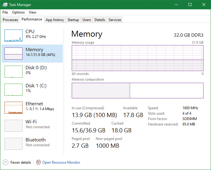
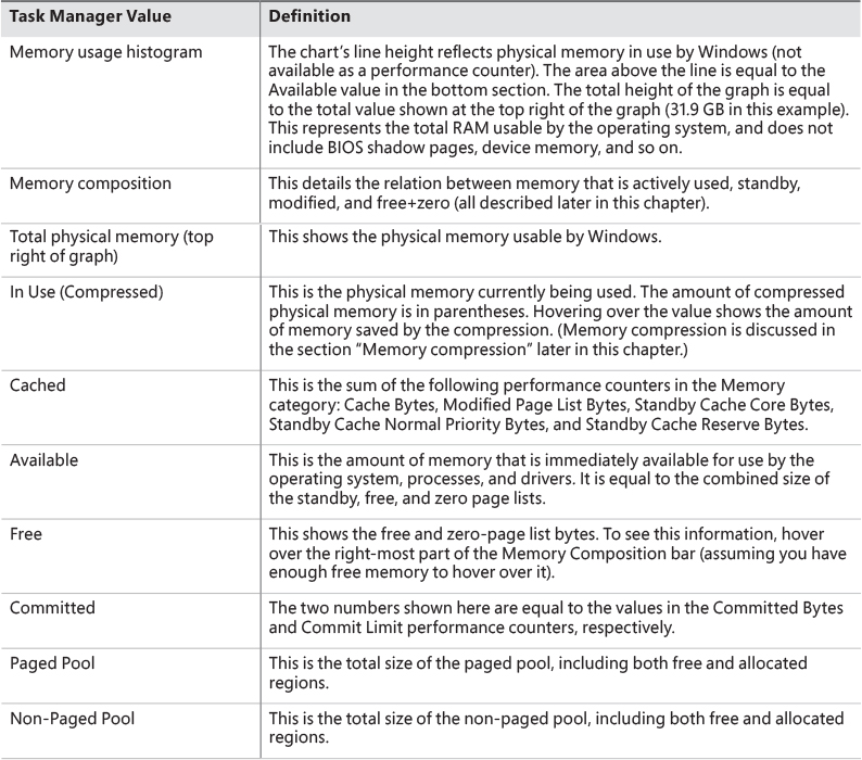
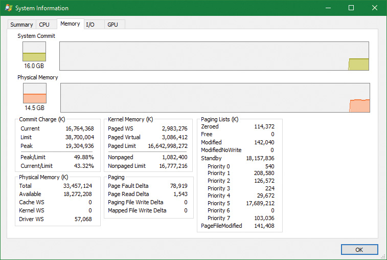
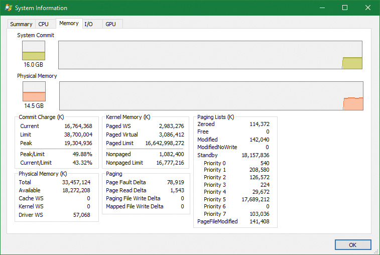
The Memory and Process performance-counter categories provide access to most of the details about system and process memory utilization. Throughout this chapter, we’ll include references to specific performance counters that contain information related to the component being described. We’ve included relevant examples and experiments throughout the chapter. One word of caution, however: Different utilities use varying and sometimes inconsistent or confusing names when displaying memory information. The following experiment illustrates this point. (We’ll explain the terms used in this example in subsequent sections.)
EXPERIMENT: Viewing system memory information
![]() VMMap This shows the usage of virtual memory within a process to a fine level of detail.
VMMap This shows the usage of virtual memory within a process to a fine level of detail.
![]() RAMMap This shows detailed physical memory usage.
RAMMap This shows detailed physical memory usage.
lkd> !vm
Page File: \??\C:\pagefile.sys
Current: 1048576 Kb Free Space: 1034696 Kb
Minimum: 1048576 Kb Maximum: 4194304 Kb
Page File: \??\C:\swapfile.sys
Current: 16384 Kb Free Space: 16376 Kb
Minimum: 16384 Kb Maximum: 24908388 Kb
No Name for Paging File
Current: 58622948 Kb Free Space: 57828340 Kb
Minimum: 58622948 Kb Maximum: 58622948 Kb
Physical Memory: 8364281 ( 33457124 Kb)
Available Pages: 4627325 ( 18509300 Kb)
ResAvail Pages: 7215930 ( 28863720 Kb)
Locked IO Pages: 0 ( 0 Kb)
Free System PTEs: 4295013448 (17180053792 Kb)
Modified Pages: 68167 ( 272668 Kb)
Modified PF Pages: 68158 ( 272632 Kb)
Modified No Write Pages: 0 ( 0 Kb)
NonPagedPool Usage: 495 ( 1980 Kb)
NonPagedPoolNx Usage: 269858 ( 1079432 Kb)
NonPagedPool Max: 4294967296 (17179869184 Kb)
PagedPool 0 Usage: 371703 ( 1486812 Kb)
PagedPool 1 Usage: 99970 ( 399880 Kb)
PagedPool 2 Usage: 100021 ( 400084 Kb)
PagedPool 3 Usage: 99916 ( 399664 Kb)
PagedPool 4 Usage: 99983 ( 399932 Kb)
PagedPool Usage: 771593 ( 3086372 Kb)
PagedPool Maximum: 4160749568 (16642998272 Kb)
Session Commit: 12210 ( 48840 Kb)
Shared Commit: 344197 ( 1376788 Kb)
Special Pool: 0 ( 0 Kb)
Shared Process: 19244 ( 76976 Kb)
Pages For MDLs: 419675 ( 1678700 Kb)
Pages For AWE: 0 ( 0 Kb)
NonPagedPool Commit: 270387 ( 1081548 Kb)
PagedPool Commit: 771593 ( 3086372 Kb)
Driver Commit: 24984 ( 99936 Kb)
Boot Commit: 100044 ( 400176 Kb)
System PageTables: 5948 ( 23792 Kb)
VAD/PageTable Bitmaps: 18202 ( 72808 Kb)
ProcessLockedFilePages: 299 ( 1196 Kb)
Pagefile Hash Pages: 33 ( 132 Kb)
Sum System Commit: 1986816 ( 7947264 Kb)
Total Private: 2126069 ( 8504276 Kb)
Misc/Transient Commit: 18422 ( 73688 Kb)
Committed pages: 4131307 ( 16525228 Kb)
Commit limit: 9675001 ( 38700004 Kb)
...
Internal synchronization
Like all other components of the Windows executive, the memory manager is fully reentrant and supports simultaneous execution on multiprocessor systems. That is, it allows two threads to acquire resources in such a way that they don’t corrupt each other’s data. To accomplish the goal of being fully reentrant, the memory manager uses several different internal synchronization mechanisms, such as spinlocks and interlocked instructions, to control access to its own internal data structures. (Synchronization objects are discussed in Chapter 8, “System mechanisms”, in Part 2.)
Some of the system-wide resources to which the memory manager must synchronize access include:
![]() Dynamically allocated portions of the system virtual address space
Dynamically allocated portions of the system virtual address space
![]() System working sets
System working sets
![]() Kernel memory pools
Kernel memory pools
![]() The list of loaded drivers
The list of loaded drivers
![]() The list of paging files
The list of paging files
![]() Physical memory lists
Physical memory lists
![]() Image base randomization address space layout randomization (ASLR) structures
Image base randomization address space layout randomization (ASLR) structures
![]() Each individual entry in the page frame number (PFN) database
Each individual entry in the page frame number (PFN) database
Per-process memory-management data structures that require synchronization include the following:
![]() Working set lock This is held while changes are made to the working set list.
Working set lock This is held while changes are made to the working set list.
![]() Address space lock This is held whenever the address space is being changed.
Address space lock This is held whenever the address space is being changed.
Both these locks are implemented using pushlocks. These are described in Chapter 8 in Part 2.
Services provided by the memory manager
The memory manager provides a set of system services to allocate and free virtual memory, share memory between processes, map files into memory, flush virtual pages to disk, retrieve information about a range of virtual pages, change the protection of virtual pages, and lock the virtual pages into memory.
Like other Windows executive services, memory-management services allow their caller to supply a process handle indicating the particular process whose virtual memory is to be manipulated. The caller can thus manipulate either its own memory or (with proper permissions) the memory of another process. For example, if a process creates a child process, by default it has the right to manipulate the child process’s virtual memory. Thereafter, the parent process can allocate, deallocate, read, and write memory on behalf of the child process by calling virtual memory services and passing a handle to the child process as an argument. This feature is used by subsystems to manage the memory of their client processes. It is also essential for implementing debuggers because debuggers must be able to read and write to the memory of the process being debugged.
Most of these services are exposed through the Windows API. As shown in Figure 5-1, the Windows API has four groups of functions for managing memory in applications:
![]() Virtual API This is the lowest-level API for general memory allocations and deallocations. It always works on page granularity. It is also the most powerful, supporting the full capabilities of the memory manager. Functions include
Virtual API This is the lowest-level API for general memory allocations and deallocations. It always works on page granularity. It is also the most powerful, supporting the full capabilities of the memory manager. Functions include VirtualAlloc, VirtualFree, VirtualProtect, VirtualLock, and others.
![]() Heap API This provides functions for small allocations (typically less than a page). It uses the Virtual API internally, but adds management on top of it. Heap manager functions include
Heap API This provides functions for small allocations (typically less than a page). It uses the Virtual API internally, but adds management on top of it. Heap manager functions include HeapAlloc, HeapFree, HeapCreate, HeapReAlloc and others. The heap manager is discussed in the section “Heap manager” later in this chapter.
![]() Local/Global APIs These are leftovers from 16-bit Windows and are now implemented using the Heap API.
Local/Global APIs These are leftovers from 16-bit Windows and are now implemented using the Heap API.
![]() Memory-mapped files These functions allow mapping files as memory and/or sharing memory between cooperating processes. Memory-mapped file functions include
Memory-mapped files These functions allow mapping files as memory and/or sharing memory between cooperating processes. Memory-mapped file functions include CreateFileMapping, OpenFileMapping, MapViewOfFile, and others.
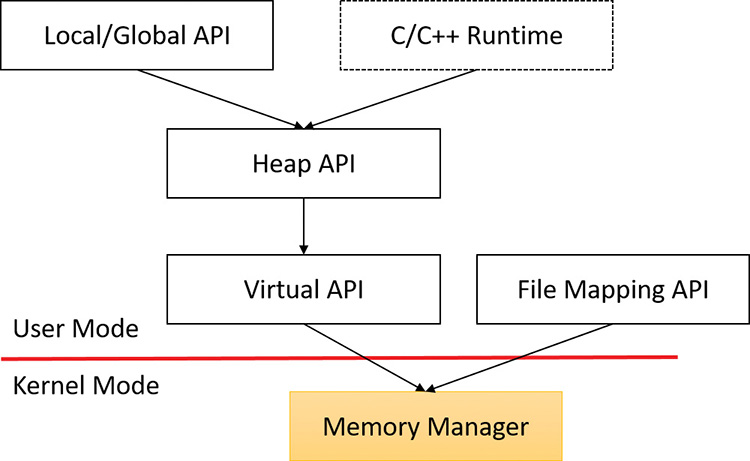
The dotted box shows a typical C/C++ runtime implementation of memory management (functions such as malloc, free, realloc, C++ operator new and delete) using the Heap API. The box is dotted because this implementation is compiler-dependent and certainly not mandatory (although quite common). The C runtime equivalents that are implemented in Ntdll.dll use the Heap API.
The memory manager also provides several services to other kernel-mode components inside the executive as well as to device drivers. These include allocating and deallocating physical memory and locking pages in physical memory for direct memory access (DMA) transfers. These functions begin with the prefix Mm. In addition, although not strictly part of the memory manager, some executive support routines that begin with Ex are used to allocate and deallocate from the system heaps (paged and non-paged pool) as well as to manipulate look-aside lists. We’ll touch on these topics later in this chapter in the section “Kernel-mode heaps (system memory pools).”
Page states and memory allocations
Pages in a process virtual address space are either free, reserved, committed, or shareable. Committed and shareable pages are pages that, when accessed, ultimately translate to valid pages in physical memory. Committed pages are also referred to as private pages. This is because committed pages cannot be shared with other processes, whereas shareable pages can be (but might be in use by only one process).
Private pages are allocated through the Windows VirtualAlloc, VirtualAllocEx, and Virtual-AllocExNuma functions, which lead eventually to the executive in the function NtAllocateVirtualMemory inside the memory manager. These functions are capable of committing memory as well as reserving memory. Reserving memory means setting aside a range of contiguous virtual addresses for possible future use (such as an array) while consuming negligible system resources, and then committing portions of the reserved space as needed as the application runs. Or, if the size requirements are known in advance, a process can reserve and commit in the same function call. In either case, the resulting committed pages can then be accessed by any thread in the process. Attempting to access free or reserved memory results in an access violation exception because the page isn’t mapped to any storage that can resolve the reference.
If committed (private) pages have never been accessed before, they are created at the time of first access as zero-initialized pages (or demand zero). Private committed pages may later be automatically written to the paging file by the operating system if required by demand for physical memory. Private refers to the fact that these pages are normally inaccessible to any other process.
![]() Note
Note
Some functions, such as ReadProcessMemory and WriteProcessMemory, appear to permit cross-process memory access, but these are implemented by running kernel-mode code in the context of the target process. (This is referred to as attaching to the process.) They also require that the security descriptor of the target process grant the accessor the PROCESS_VM_READ or PROCESS_VM_WRITE right, respectively, or that the accessor holds the SeDebugPrivilege, which is by default granted only to members of the administrators group.
Shared pages are usually mapped to a view of a section. This in turn is part or all of a file, but may instead represent a portion of page file space. All shared pages can potentially be shared with other processes. Sections are exposed in the Windows API as file-mapping objects.
When a shared page is first accessed by any process, it will be read in from the associated mapped file unless the section is associated with the paging file, in which case it is created as a zero-initialized page. Later, if it is still resident in physical memory, the second and subsequent processes accessing it can simply use the same page contents that are already in memory. Shared pages might also have been prefetched by the system.
Two upcoming sections of this chapter, “Shared memory and mapped files” and “Section objects,” go into much more detail about shared pages. Pages are written to disk through a mechanism called modified page writing. This occurs as pages are moved from a process’s working set to a system-wide list called the modified page list. From there, they are written to disk or remote storage. (Working sets and the modified list are explained later in this chapter.) Mapped file pages can also be written back to their original files on disk with an explicit call to FlushViewOfFile or by the mapped page writer as memory demands dictate.
You can decommit private pages and/or release address space with the VirtualFree or VirtualFreeEx function. The difference between decommittal and release is similar to the difference between reservation and committal. Decommitted memory is still reserved, but released memory has been freed; it is neither committed nor reserved.
Using the two-step process of reserving and then committing virtual memory defers committing pages—and, thereby, defers adding to the system commit charge described in the next section—until needed, but keeps the convenience of virtual contiguity. Reserving memory is a relatively inexpensive operation because it consumes very little actual memory. All that needs to be updated or constructed is the relatively small internal data structures that represent the state of the process address space. We’ll explain these data structures, called page tables and Virtual Address Descriptors (VADs), later in this chapter.
One extremely common use for reserving a large space and committing portions of it as needed is the user-mode stack for each thread. When a thread is created, a stack is created by reserving a contiguous portion of the process address space. (The default size is 1 MB but you can override this size with the CreateThread and CreateRemoteThread(Ex) function calls or change it on an executable image basis by using the /STACK linker flag.) By default, the initial page in the stack is committed and the next page is marked as a guard page (which isn’t committed) that traps references beyond the end of the committed portion of the stack and expands it.
EXPERIMENT: Reserved versus committed pages
1. Open two command prompt windows.
2. Invoke TestLimit in one of the command prompt windows to create a large amount of reserved memory:
C:\temp>testlimit -r 1 -c 800
Testlimit v5.24 - test Windows limits
Copyright (C) 2012-2015 Mark Russinovich
Sysinternals - wwww.sysinternals.com
Process ID: 18468
Reserving private bytes 1 MB at a time ...
Leaked 800 MB of reserved memory (800 MB total leaked). Lasterror: 0
The operation completed successfully.
3. In the other command prompt window, create a similar amount of committed memory:
C:\temp>testlimit -m 1 -c 800
Testlimit v5.24 - test Windows limits
Copyright (C) 2012-2015 Mark Russinovich
Sysinternals - wwww.sysinternals.com
Process ID: 14528
Leaking private bytes 1 KB at a time ...
Leaked 800 MB of private memory (800 MB total leaked). Lasterror: 0
The operation completed successfully.
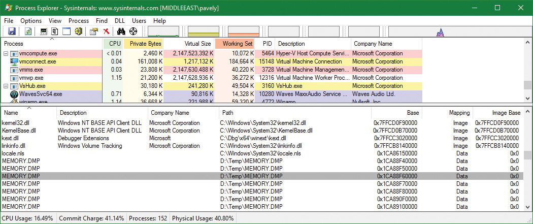
4. Run Task Manager, click the Details tab, and add a Commit Size column.
5. Find the two instances of TestLimit.exe in the list. They should look something like the following:
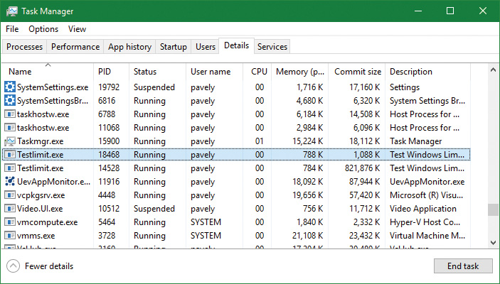
6. Notice that Task Manager shows the committed size but it has no counters that reveal the reserved memory in the other TestLimit process.
8. Click the Process Memory tab and enable the Private Bytes and Virtual Size columns.
9. Find the two TestLimit.exe processes in the main display:
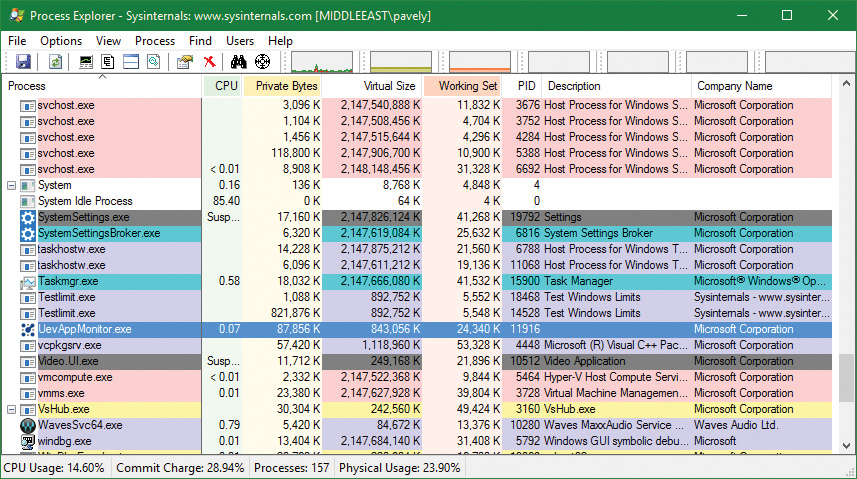
10. Notice that the virtual sizes of the two processes are identical, but only one shows a Private Bytes value that is comparable to the Virtual Size value. The large difference in the other TestLimit process (process ID 18468) is due to the reserved memory. You could make the same comparison in Performance Monitor by looking at the Virtual Bytes and Private Bytes counters in the Process category.
Commit charge and commit limit
On the Performance tab in Task Manager, on the Memory page, there is a Committed label with two numbers underneath it. The memory manager keeps track of private committed memory usage on a global basis, termed commitment or commit charge. This is the first of the two numbers, which represents the total of all committed virtual memory in the system.
There is a system-wide limit, called the system commit limit or simply the commit limit, on the amount of committed virtual memory that can exist at any one time. This limit corresponds to the current total size of all paging files plus the amount of RAM that is usable by the operating system. This is the second of the two numbers displayed under the Committed label. The memory manager can increase the commit limit automatically by expanding one or more of the paging files if they are not already at their configured maximum size.
Commit charge and the system commit limit are explained in more detail in the section “Commit charge and the system commit limit” later in this chapter.
Locking memory
In general, it’s better to let the memory manager decide which pages remain in physical memory. However, there might be special circumstances when it might be necessary for an application or device driver to lock pages in physical memory. Pages can be locked in memory in two ways:
![]() Windows applications can call the
Windows applications can call the VirtualLock function to lock pages in their process working set. Pages locked using this mechanism remain in memory until explicitly unlocked or until the process that locked them terminates. The number of pages a process can lock can’t exceed its minimum working set size minus eight pages. If a process needs to lock more pages, it can increase its working set minimum with the SetProcessWorkingSetSizeEx function, discussed later in this chapter in the section “Working set management.”
![]() Device drivers can call the
Device drivers can call the MmProbeAndLockPages, MmLockPagableCodeSection, MmLockPagable-DataSection, or MmLockPagableSectionByHandle kernel-mode functions. Pages locked using this mechanism remain in memory until explicitly unlocked. The last three of these APIs enforce no quota on the number of pages that can be locked in memory because the resident available page charge is obtained when the driver first loads. This ensures that it can never cause a system crash due to overlocking. For the first API, quota charges must be obtained or the API will return a failure status.
Allocation granularity
Windows aligns each region of reserved process address space to begin on an integral boundary defined by the value of the system allocation granularity, which can be retrieved from the Windows GetSystemInfo or GetNativeSystemInfo functions. This value is 64 KB, a granularity that is used by the memory manager to efficiently allocate metadata (for example, VADs, bitmaps, and so on) to support various process operations. In addition, if support were added for future processors with larger page sizes (for example, up to 64 KB) or virtually indexed caches that require system-wide physical-to-virtual page alignment, the risk of requiring changes to applications that made assumptions about allocation alignment would be reduced.
![]() Note
Note
Windows kernel-mode code isn’t subject to the same restrictions. It can reserve memory on a single-page granularity (although this is not exposed to device drivers for the reasons detailed earlier). This level of granularity is primarily used to pack TEB allocations more densely. Because this mechanism is internal only, this code can easily be changed if a future platform requires different values. Also, for the purposes of supporting 16-bit and MS-DOS applications on x86 systems only, the memory manager provides the MEM_DOS_LIM flag to the MapViewOfFileEx API, which is used to force the use of single-page granularity.
Finally, when a region of address space is reserved, Windows ensures that the size and base of the region is a multiple of the system page size, whatever that might be. For example, because x86 systems use 4 KB pages, if you tried to reserve a region of memory 18 KB in size, the actual amount reserved on an x86 system would be 20 KB. If you specified a base address of 3 KB for an 18 KB region, the actual amount reserved would be 24 KB. Note that the VAD for the allocation would then also be rounded to 64 KB alignment/length, thus making the remainder of it inaccessible.
Shared memory and mapped files
As is true with most modern operating systems, Windows provides a mechanism to share memory among processes and the operating system. Shared memory can be defined as memory that is visible to more than one process or that is present in more than one process virtual address space. For example, if two processes use the same DLL, it would make sense to load the referenced code pages for that DLL into physical memory only once and share those pages between all processes that map the DLL, as illustrated in Figure 5-2.
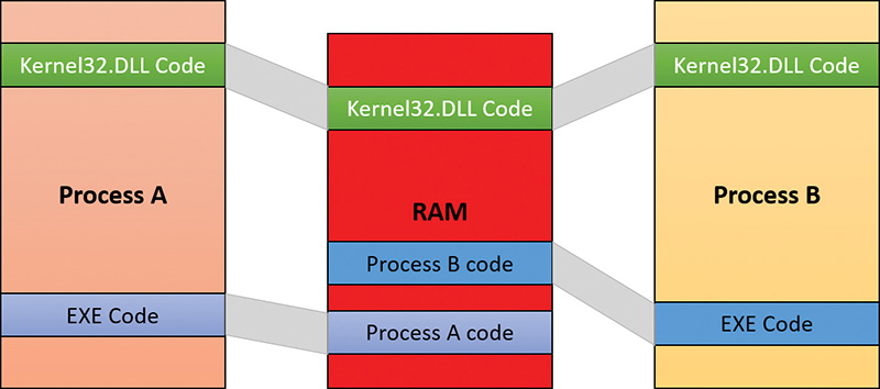
Each process would still maintain its private memory areas to store private data but the DLL code and unmodified data pages could be shared without harm. As we’ll explain later, this kind of sharing happens automatically because the code pages in executable images—EXE and DLL files, and several other types like screen savers (SCR), which are essentially DLLs under other names—are mapped as execute-only and writable pages are mapped as copy-on-write. (See the “Copy-on-write” section later in this chapter for more information.)
Figure 5-2 shows two processes, based on different images, that share a DLL mapped just once to physical memory. The images (EXE) code itself is not shared in this case because the two processes run different images. The EXE code would be shared between processes that run the same image, such as two or more processes running Notepad.exe.
The underlying primitives in the memory manager used to implement shared memory are called section objects, which are exposed as file-mapping objects in the Windows API. The internal structure and implementation of section objects are described later in this chapter in the section “Section objects.”
This fundamental primitive in the memory manager is used to map virtual addresses whether in main memory, in the page file, or in some other file that an application wants to access as if it were in memory. A section can be opened by one process or by many. In other words, section objects don’t necessarily equate to shared memory.
A section object can be connected to an open file on disk (called a mapped file) or to committed memory (to provide shared memory). Sections mapped to committed memory are called page-file-backed sections because the pages are written to the paging file (as opposed to a mapped file) if demands on physical memory require it. (Because Windows can run with no paging file, page-file-backed sections might in fact be “backed” only by physical memory.) As with any other empty page that is made visible to user mode (such as private committed pages), shared committed pages are always zero-filled when they are first accessed to ensure that no sensitive data is ever leaked.
To create a section object, call the Windows CreateFileMapping, CreateFileMappingFromApp, or CreateFileMappingNuma(Ex) function, specifying a previously opened file handle to map it to (or INVALID_HANDLE_VALUE for a page-file-backed section) and optionally a name and security descriptor. If the section has a name, other processes can open it with OpenFileMapping or the CreateFileMapping* functions. Or you can grant access to section objects through either handle inheritance (by specifying that the handle be inheritable when opening or creating the handle) or handle duplication (by using DuplicateHandle). Device drivers can also manipulate section objects with the ZwOpenSection, ZwMapViewOfSection, and ZwUnmapViewOfSection functions.
A section object can refer to files that are much larger than can fit in the address space of a process. (If the paging file backs a section object, sufficient space must exist in the paging file and/or RAM to contain it.) To access a very large section object, a process can map only the portion of the section object that it requires (called a view of the section) by calling the MapViewOfFile(Ex), MapViewOfFileFromApp, or MapViewOfFileExNuma function and then specifying the range to map. Mapping views permits processes to conserve address space because only the views of the section object needed at the time must be mapped into memory.
Windows applications can use mapped files to conveniently perform I/O to files by simply making them appear as data in memory within their address space. User applications aren’t the only consumers of section objects; the image loader uses section objects to map executable images, DLLs, and device drivers into memory, and the cache manager uses them to access data in cached files. (For information on how the cache manager integrates with the memory manager, see Chapter 14 in Part 2.) The implementation of shared memory sections, both in terms of address translation and the internal data structures, is explained in the section “Section objects” later in this chapter.
Protecting memory
As explained in Chapter 1, “Concepts and tools,” Windows provides memory protection so that no user process can inadvertently or deliberately corrupt the address space of another process or the operating system. Windows provides this protection in four primary ways.
![]() All system-wide data structures and memory pools used by kernel-mode system components can be accessed only while in kernel mode. User-mode threads can’t access these pages. If they attempt to do so, the hardware generates a fault, which the memory manager reports to the thread as an access violation.
All system-wide data structures and memory pools used by kernel-mode system components can be accessed only while in kernel mode. User-mode threads can’t access these pages. If they attempt to do so, the hardware generates a fault, which the memory manager reports to the thread as an access violation.
![]() Each process has a separate, private address space, protected from access by any thread belonging to another process. Even shared memory is not really an exception to this because each process accesses the shared regions using addresses that are part of its own virtual address space. The only exception is if another process has virtual memory read or write access to the process object (or holds
Each process has a separate, private address space, protected from access by any thread belonging to another process. Even shared memory is not really an exception to this because each process accesses the shared regions using addresses that are part of its own virtual address space. The only exception is if another process has virtual memory read or write access to the process object (or holds SeDebugPrivilege) and thus can use the ReadProcessMemory or WriteProcessMemory function. Each time a thread references an address, the virtual memory hardware, in concert with the memory manager, intervenes and translates the virtual address into a physical one. By controlling how virtual addresses are translated, Windows can ensure that threads running in one process don’t inappropriately access a page belonging to another process.
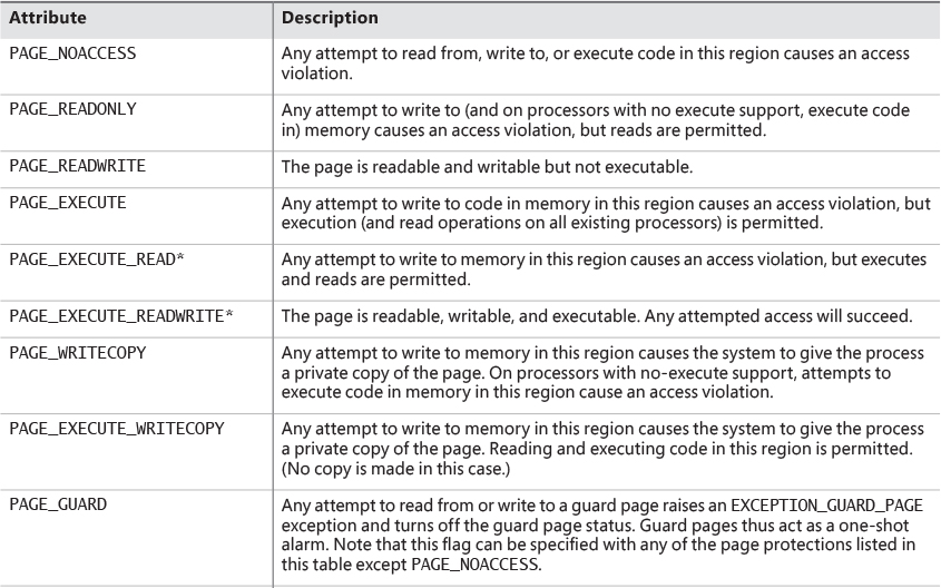
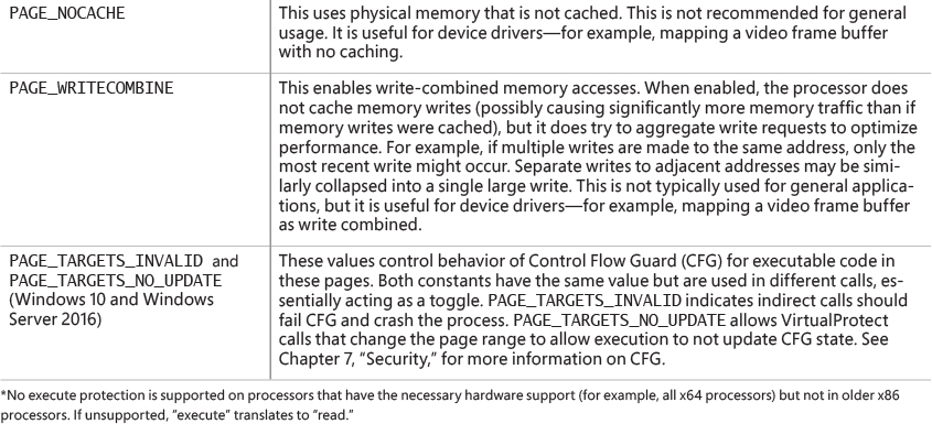
![]() In addition to the implicit protection offered by virtual-to-physical address translation, all processors supported by Windows provide some form of hardware-controlled memory protection such as read/write, read-only, and so on. (The exact details of such protection vary according to the processor.) For example, code pages in the address space of a process are marked read-only and are thus protected from modification by user threads. Table 5-2 lists the memory-protection options defined in the Windows API. (See the documentation for the
In addition to the implicit protection offered by virtual-to-physical address translation, all processors supported by Windows provide some form of hardware-controlled memory protection such as read/write, read-only, and so on. (The exact details of such protection vary according to the processor.) For example, code pages in the address space of a process are marked read-only and are thus protected from modification by user threads. Table 5-2 lists the memory-protection options defined in the Windows API. (See the documentation for the VirtualProtect, Virtual-ProtectEx, VirtualQuery, and VirtualQueryEx functions.)
![]() Shared memory section objects have standard Windows access control lists (ACLs) that are checked when processes attempt to open them, thus limiting access of shared memory to those processes with the proper rights. Access control also comes into play when a thread creates a section to contain a mapped file. To create the section, the thread must have at least read access to the underlying file object or the operation will fail.
Shared memory section objects have standard Windows access control lists (ACLs) that are checked when processes attempt to open them, thus limiting access of shared memory to those processes with the proper rights. Access control also comes into play when a thread creates a section to contain a mapped file. To create the section, the thread must have at least read access to the underlying file object or the operation will fail.
Once a thread has successfully opened a handle to a section, its actions are still subject to the memory manager and the hardware-based page protections described earlier. A thread can change the page-level protection on virtual pages in a section if the change doesn’t violate the permissions in the ACL for that section object. For example, the memory manager allows a thread to change the pages of a read-only section to have copy-on-write access but not to have read/write access. The copy-on-write access is permitted because it has no effect on other processes sharing the data.
Data Execution Prevention
Data Execution Prevention (DEP), or no-execute (NX) page protection, causes an attempt to transfer control to an instruction in a page marked as “no execute” to generate an access fault. This can prevent certain types of malware from exploiting bugs in the system through the execution of code placed in a data page such as the stack. DEP can also catch poorly written programs that don’t correctly set permissions on pages from which they intend to execute code. If an attempt is made in kernel mode to execute code in a page marked as “no execute,” the system will crash with the bug check code ATTEMPTED_ EXECUTE_OF_NOEXECUTE_MEMORY (0xFC). (See Chapter 15, “Crash dump analysis,” in Part 2 for an explanation of these codes.) If this occurs in user mode, a STATUS_ACCESS_VIOLATION (0xC0000005) exception is delivered to the thread attempting the illegal reference. If a process allocates memory that needs to be executable, it must explicitly mark such pages by specifying the PAGE_EXECUTE, PAGE_EXECUTE_READ, PAGE_EXECUTE_READWRITE, or PAGE_EXECUTE_WRITECOPY flags on the page-granularity memory-allocation functions.
On 32-bit x86 systems that support DEP, bit 63 in the page table entry (PTE) is used to mark a page as non-executable. Therefore, the DEP feature is available only when the processor is running in Physical Address Extension (PAE) mode, without which page table entries are only 32 bits wide. (See the section “x86 virtual address translation” later in this chapter.) Thus, support for hardware DEP on 32-bit systems requires loading the PAE kernel (%SystemRoot%\System32\Ntkrnlpa.exe), which currently is the only supported kernel on x86 systems.
On ARM systems, DEP is set to AlwaysOn.
On 64-bit versions of Windows, execution protection is always applied to all 64-bit processes and device drivers and can be disabled only by setting the nx BCD option to AlwaysOff. Execution protection for 32-bit programs depends on system configuration settings, described shortly. On 64-bit Windows, execution protection is applied to thread stacks (both user and kernel mode), user-mode pages not specifically marked as executable, the kernel paged pool, and the kernel session pool. For a description of kernel memory pools, see the section “Kernel-mode heaps (system memory pools).” However, on 32-bit Windows, execution protection is applied only to thread stacks and user-mode pages, not to the paged pool and session pool.
The application of execution protection for 32-bit processes depends on the value of the BCD nx option. To change the settings, open the Data Execution Prevention tab in the Performance Options dialog box (see Figure 5-3). (To open this dialog box, right-click Computer, select Properties, click Advanced System Settings, and choose Performance Settings.) When you configure no-execute protection in the Performance Options dialog box, the BCD nx option is set to the appropriate value. Table 5-3 lists the variations of the values and how they correspond to the Data Execution Prevention tab. The registry lists 32-bit applications that are excluded from execution protection under the HKLM\SOFTWARE\Microsoft\Windows NT\CurrentVersion\AppCompatFlags\Layers key, with the value name being the full path of the executable and the data set to DisableNXShowUI.
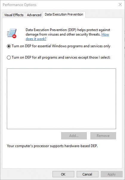
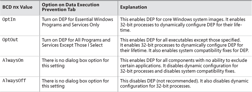
On Windows client versions (both 64-bit and 32-bit), execution protection for 32-bit processes is configured by default to apply only to core Windows operating system executables. That is, the nx BCD option is set to OptIn. This is to avoid breaking 32-bit applications that might rely on being able to execute code in pages not specifically marked as executable, such as self-extracting or packed applications. On Windows server systems, execution protection for 32-bit applications is configured by default to apply to all 32-bit programs. That is, the nx BCD option is set to OptOut.
Even if you force DEP to be enabled, there are still other methods through which applications can disable DEP for their own images. For example, regardless of which execution-protection options are enabled, the image loader will verify the signature of the executable against known copy-protection mechanisms (such as SafeDisc and SecuROM) and disable execution protection to provide compatibility with older copy-protected software such as computer games. (See Chapter 3 for more information about the image loader.)
EXPERIMENT: Looking at DEP protection on processes
![]() DEP (permanent) This means the process has enabled DEP because it is a “necessary Windows program or service.”
DEP (permanent) This means the process has enabled DEP because it is a “necessary Windows program or service.”
![]() DEP This means the process opted in to DEP. This may be due to a system-wide policy to opt in to all 32-bit processes, because of an API call such as
DEP This means the process opted in to DEP. This may be due to a system-wide policy to opt in to all 32-bit processes, because of an API call such as SetProcessDEPPolicy, or because the /NXCOMPAT linker flag was set when the image was built.
![]() Nothing If the column displays no information for this process, DEP is disabled because of either a system-wide policy or an explicit API call or shim.
Nothing If the column displays no information for this process, DEP is disabled because of either a system-wide policy or an explicit API call or shim.
Additionally, to provide compatibility with older versions of the Active Template Library (ATL) framework (version 7.1 or earlier), the Windows kernel provides an ATL thunk emulation environment. This environment detects ATL thunk code sequences that have caused the DEP exception and emulates the expected operation. Application developers can request that ATL thunk emulation not be applied by using the latest Microsoft C++ compiler and specifying the /NXCOMPAT flag (which sets the IMAGE_DLLCHARACTERISTICS_NX_COMPAT flag in the PE header), which tells the system that the executable fully supports DEP. Note that ATL thunk emulation is permanently disabled if the AlwaysOn value is set.
Finally, if the system is in OptIn or OptOut mode and executing a 32-bit process, the SetProcessDEPPolicy function allows a process to dynamically disable DEP or to permanently enable it. When it is enabled through this API, DEP cannot be disabled programmatically for the lifetime of the process. This function can also be used to dynamically disable ATL thunk emulation if the image wasn’t compiled with the /NXCOMPAT flag. On 64-bit processes or systems booted with AlwaysOff or AlwaysOn, the function always returns a failure. The GetProcessDEPPolicy function returns the 32-bit per-process DEP policy (it fails on 64-bit systems, where the policy is always the same—enabled), while GetSystemDEPPolicy can be used to return a value corresponding to the policies in Table 5-3.
Copy-on-write
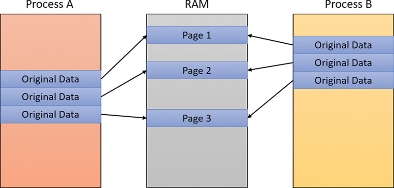
Copy-on-write page protection is an optimization the memory manager uses to conserve physical memory. When a process maps a copy-on-write view of a section object that contains read/write pages, the memory manager delays the copying of pages until the page is written to instead of making a process private copy at the time the view is mapped. For example, in Figure 5-4, two processes are sharing three pages, each marked copy-on-write, but neither of the two processes has attempted to modify any data on the pages.
If a thread in either process writes to a page, a memory-management fault is generated. The memory manager sees that the write is to a copy-on-write page, so instead of reporting the fault as an access violation, it does the following:
1. It allocates a new read/write page in physical memory.
2. It copies the contents of the original page to the new page.
3. It updates the corresponding page-mapping information (explained later in this chapter) in this process to point to the new location.
4. It dismisses the exception, causing the instruction that generated the fault to be re-executed.
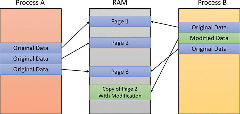
This time, the write operation succeeds. However, as shown in Figure 5-5, the newly copied page is now private to the process that did the writing and isn’t visible to the other process still sharing the copy-on-write page. Each new process that writes to that same shared page will also get its own private copy.
One application of copy-on-write is to implement breakpoint support in debuggers. For example, by default, code pages start out as execute-only. If a programmer sets a breakpoint while debugging a program, however, the debugger must add a breakpoint instruction to the code. It does this by first changing the protection on the page to PAGE_EXECUTE_READWRITE and then changing the instruction stream. Because the code page is part of a mapped section, the memory manager creates a private copy for the process with the breakpoint set, while other processes continue using the unmodified code page.
Copy-on-write is one example of an evaluation technique called lazy evaluation that the memory manager uses as often as possible. Lazy-evaluation algorithms avoid performing an expensive operation until absolutely required. If the operation is never required, no time is wasted on it.
To examine the rate of copy-on-write faults, see the Write Copies/Sec performance counter in the Memory category of the Performance Monitor tool.
Address Windowing Extensions
Although the 32-bit version of Windows can support up to 64 GB of physical memory (refer to Table 2-2), each 32-bit user process has only a 2 GB virtual address space by default. (You can configure this to up to 3 GB when using the increaseuserva BCD option, described in the upcoming section “Virtual address space layouts.”) An application that needs to make more than 2 GB (or 3 GB) of data easily available in a single process could do so via file mapping, remapping a part of its address space into various portions of a large file. However, significant paging would be involved upon each remap.
For higher performance (and more fine-grained control), Windows provides a set of functions called Address Windowing Extensions (AWE). These functions allow a process to allocate more physical memory than can be represented in its virtual address space. It then can access the physical memory by mapping a portion of its virtual address space into selected portions of the physical memory at various times.
You allocate and use memory via the AWE functions in three steps:
1. You allocate the physical memory to be used. The application uses the Windows functions AllocateUserPhysicalPages or AllocateUserPhysicalPagesNuma. (These require the SeLockMemoryPrivilege.)
2. You create one or more regions of virtual address space to act as windows to map views of the physical memory. The application uses the Win32 VirtualAlloc, VirtualAllocEx, or Virtual-AllocExNuma function with the MEM_PHYSICAL flag.
3. Steps 1 and 2 are, generally speaking, initialization steps. To actually use the memory, the application uses MapUserPhysicalPages or MapUserPhysicalPagesScatter to map a portion of the physical region allocated in step 1 into one of the virtual regions, or windows, allocated in step 2.
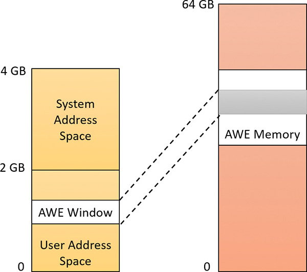
Figure 5-6 shows an example. The application has created a 256 MB window in its address space and has allocated 4 GB of physical memory. It can then use MapUserPhysicalPages or MapUserPhysical-PagesScatter to access any portion of the physical memory by mapping the desired portion of memory into the 256 MB window. The size of the application’s virtual address space window determines the amount of physical memory the application can access with any given mapping. To access another portion of the allocated RAM, the application can simply remap the area.
The AWE functions exist on all editions of Windows and are usable regardless of how much physical memory a system has. However, AWE is most useful on 32-bit systems with more than 2 GB of physical memory because it provides a way for a 32-bit process to access more RAM than its virtual address space would otherwise allow. Another use is for security purposes. Because AWE memory is never paged out, the data in AWE memory can never have a copy in the paging file that someone could examine by rebooting into an alternate operating system. (VirtualLock provides the same guarantee for pages in general.)
Finally, there are some restrictions on memory allocated and mapped by the AWE functions:
![]() Pages can’t be shared between processes.
Pages can’t be shared between processes.
![]() The same physical page can’t be mapped to more than one virtual address.
The same physical page can’t be mapped to more than one virtual address.
![]() Page protection is limited to read/write, read-only, and no access.
Page protection is limited to read/write, read-only, and no access.
AWE is less useful on 64 bit Windows systems because these systems support 128 TB of virtual address space per process, while allowing a maximum of only 24 TB of RAM (on Windows Server 2016 systems). Therefore, AWE is not necessary to allow an application to use more RAM than it has virtual address space; the amount of RAM on the system will always be smaller than the process virtual address space. AWE remains useful, however, for setting up non-pageable regions of a process address space. It provides finer granularity than the file-mapping APIs. (The system page size is 4 KB rather than 64 KB.)
For a description of the page table data structures used to map memory on systems with more than 4 GB of physical memory, see the section “x86 virtual address translation.”
Kernel-mode heaps (system memory pools)
At system initialization, the memory manager creates two dynamically sized memory pools, or heaps, that most kernel-mode components use to allocate system memory:
![]() Non-paged pool This consists of ranges of system virtual addresses that are guaranteed to reside in physical memory at all times. Thus, they can be accessed at any time without incurring a page fault—meaning they can be accessed from any IRQL. One of the reasons a non-paged pool is required is because page faults can’t be satisfied at DPC/dispatch level or above. Therefore, any code and data that might execute or be accessed at or above DPC/dispatch level must be in non-pageable memory.
Non-paged pool This consists of ranges of system virtual addresses that are guaranteed to reside in physical memory at all times. Thus, they can be accessed at any time without incurring a page fault—meaning they can be accessed from any IRQL. One of the reasons a non-paged pool is required is because page faults can’t be satisfied at DPC/dispatch level or above. Therefore, any code and data that might execute or be accessed at or above DPC/dispatch level must be in non-pageable memory.
![]() Paged pool This is a region of virtual memory in system space that can be paged into and out of the system. Device drivers that don’t need to access the memory from DPC/dispatch level or above can use paged pool. It is accessible from any process context.
Paged pool This is a region of virtual memory in system space that can be paged into and out of the system. Device drivers that don’t need to access the memory from DPC/dispatch level or above can use paged pool. It is accessible from any process context.
Both memory pools are in the system part of the address space and are mapped in the virtual address space of every process. The executive provides routines to allocate and deallocate from these pools. For information on these routines, see the functions that start with ExAllocatePool, ExAllocate-PoolWithTag, and ExFreePool in the Windows Development Kit (WDK) documentation.
Systems start with four paged pools, which are combined to make the overall system paged pool, and two non-paged pools. More are created—as many as 64—depending on the number of NUMA nodes on the system. Having more than one paged pool reduces the frequency of system code blocking on simultaneous calls to pool routines. Additionally, the different pools created are mapped across different virtual address ranges that correspond to different NUMA nodes on the system. The different data structures, such as the large page look-aside lists, to describe pool allocations are also mapped across different NUMA nodes.
In addition to the paged and non-paged pools, there are a few other pools with special attributes or uses. For example, there is a pool region in session space that is used for data that is common to all processes in the session. Allocations from another pool, called special pool, are surrounded by pages marked as “no access” to help isolate problems in code that accesses memory before or after the region of pool it allocated.
Pool sizes
A non-paged pool starts at an initial size based on the amount of physical memory on the system and then grows as needed. For a non-paged pool, the initial size is 3 percent of system RAM. If this is less than 40 MB, the system will instead use 40 MB as long as 10 percent of RAM results in more than 40 MB. Otherwise, 10 percent of RAM is chosen as a minimum. Windows dynamically chooses the maximum size of the pools and allows a given pool to grow from its initial size to the maximums shown in Table 5-4.
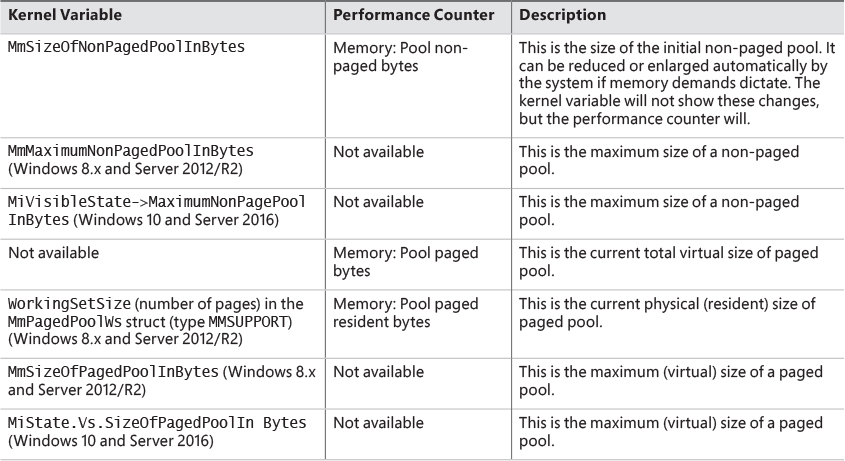
Four of these computed sizes are stored in kernel variables in Windows 8.x and Server 2012/R2. Three of these are exposed as performance counters and one is computed only as a performance counter value. Windows 10 and Server 2016 moved the global variables into fields in a global memory management structure (MI_SYSTEM_INFORMATION) named MiState. Within this lies a variable named Vs (of type _MI_VISIBLE_STATE) where this information resides. The global variable MiVisibleState also points to that Vs member. These variables and counters are listed in Table 5-5.
EXPERIMENT: Determining the maximum pool sizes
For Process Explorer to retrieve this information, it must have access to the symbols for the kernel running on your system. For a description of how to configure Process Explorer to use symbols, see the experiment “Viewing process details with Process Explorer” in Chapter 1.
Monitoring pool usage
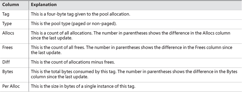
The Memory performance counter object has separate counters for the non-paged pool and paged pool (both virtual and physical). In addition, the Poolmon utility (in the WDK Tools directory) allows you to monitor the detailed usage of non-paged and paged pool. When you run Poolmon, you should see a display like the one shown in Figure 5-7.
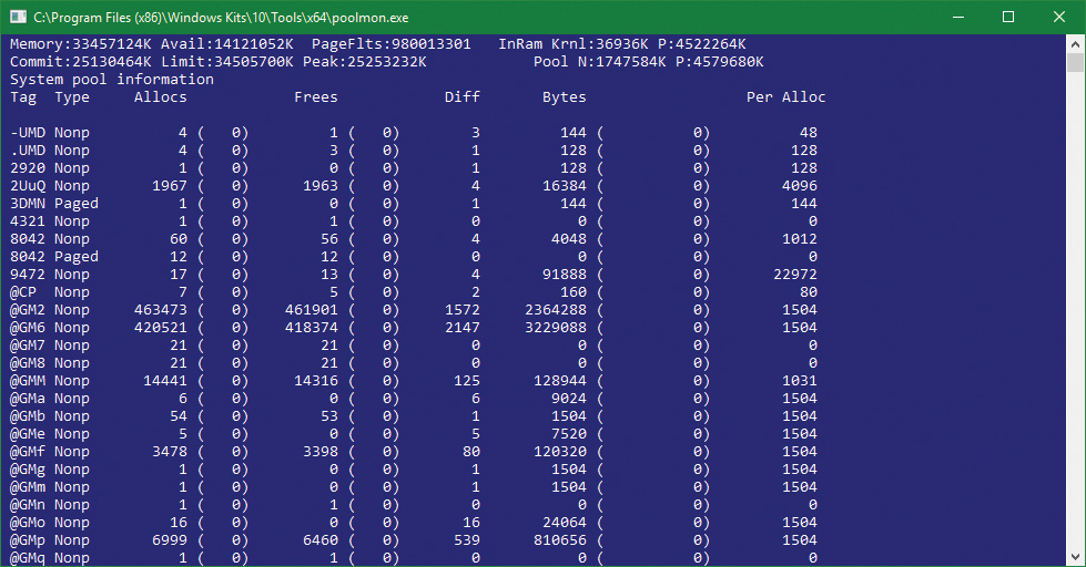
Any highlighted lines you might see represent changes to the display. (You can disable the highlighting feature by typing / while running Poolmon; type / again to re-enable highlighting.) Type ? while Poolmon is running to bring up its help screen. You can configure which pools you want to monitor (paged, non-paged, or both) and the sort order. For example, by pressing the P key until only non-paged allocations are shown, and then the D key to sort by the Diff (differences) column, you can find out what kind of structures are most numerous in non-paged pool. Also, the command-line options are shown, which allow you to monitor specific tags (or every tag but one tag). For example, the command poolmon –iCM will monitor only CM tags (allocations from the configuration manager, which manages the registry). The columns have the meanings shown in Table 5-6.
For a description of the meaning of the pool tags used by Windows, see the Pooltag.txt file in the Triage subdirectory where the Debugging tools for Windows are located. Because third-party device-driver pool tags are not listed in this file, you can use the –c switch on the 32-bit version of Poolmon that comes with the WDK to generate a local pool tag file (Localtag.txt). This file will contain pool tags used by drivers found on your system, including third-party drivers. (Note that if a device-driver binary has been deleted after it was loaded, its pool tags will not be recognized.)
Alternatively, you can search the device drivers on your system for a pool tag by using the Strings.exe tool from Sysinternals. For example, the following command displays drivers that contain the string "abcd":
strings %SYSTEMROOT%\system32\drivers\*.sys | findstr /i "abcd"
Device drivers do not necessarily have to be located in %SystemRoot%\System32\Drivers. They can be in any folder. To list the full path of all loaded drivers, follow these steps:
1. Open the Start menu and type Msinfo32 (System Information should appear).
2. Run System Information.
3. Select Software Environment.
4. Choose System Drivers. If a device driver has been loaded and then deleted from the system, it will not be listed here.
An alternative way to view pool usage by device driver is to enable the pool-tracking feature of Driver Verifier, explained in Chapter 6. While this makes the mapping from pool tag to device driver unnecessary, it does require a reboot (to enable Driver Verifier on the desired drivers). After rebooting with pool tracking enabled, you can either run the graphical Driver Verifier Manager (%SystemRoot%\System32\Verifier.exe) or use the Verifier /Log command to send the pool-usage information to a file.
Finally, you can view pool usage with the kernel debugger !poolused command. The !poolused 2 command shows non-paged pool usage sorted by pool tag using the most amount of pool. The !poolused 4 command lists paged-pool usage, again sorted by pool tag using the most amount of pool. The following example shows the partial output from these two commands:
lkd> !poolused 2
........
Sorting by NonPaged Pool Consumed
NonPaged Paged
Tag Allocs Used Allocs Used
File 626381 260524032 0 0 File objects
Ntfx 733204 227105872 0 0 General Allocation , Binary:
ntfs.sys
MmCa 513713 148086336 0 0 Mm control areas for mapped
files , Binary: nt!mm
FMsl 732490 140638080 0 0 STREAM_LIST_CTRL structure ,
Binary: fltmgr.sys
CcSc 104420 56804480 0 0 Cache Manager Shared Cache Map
, Binary: nt!cc
SQSF 283749 45409984 0 0 UNKNOWN pooltag 'SQSF', please
update pooltag.txt
FMfz 382318 42819616 0 0 FILE_LIST_CTRL structure ,
Binary: fltmgr.sys
FMsc 36130 32950560 0 0 SECTION_CONTEXT structure ,
Binary: fltmgr.sys
EtwB 517 31297568 107 105119744 Etw Buffer , Binary: nt!etw
DFmF 382318 30585440 382318 91756320 UNKNOWN pooltag 'DFmF', please
update pooltag.txt
DFmE 382318 18351264 0 0 UNKNOWN pooltag 'DFmE', please
update pooltag.txt
FSfc 382318 18351264 0 0 Unrecoginzed File System Run
Time allocations (update
pooltag.w) , Binary: nt!fsrtl
smNp 4295 17592320 0 0 ReadyBoost store node pool
allocations , Binary: nt!store
or rdyboost.sys
Thre 5780 12837376 0 0 Thread objects , Binary: nt!ps
Pool 8 12834368 0 0 Pool tables, etc.
EXPERIMENT: Troubleshooting a pool leak
1. Run Notmyfault.exe for your OS bitness (for example, the 64 bit on a 64-bit system).
2. Notmyfault.exe loads the Myfault.sys device driver and presents a Not My Fault dialog box with the Crash tab selected. Click the Leak tab. It should look something like this:
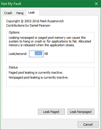
3. Ensure that the Leak/Second setting is set to 1000 KB.
4. Click the Leak Paged button. This causes Notmyfault to begin sending requests to the Myfault device driver to allocate paged pool. Notmyfault will continue sending requests until you click the Stop Paged button. Paged pool is not normally released even when you close a program that has caused it to occur (by interacting with a buggy device driver). The pool is permanently leaked until you reboot the system. However, to make testing easier, the Myfault device driver detects that the process was closed and frees its allocations.
5. While the pool is leaking, open Task Manager, click the Performance tab, and select the Memory label. Notice the Paged Pool value climbing. You can also check this with Process Explorer’s System Information display (select the View menu, choose System Information, and click the Memory tab).
6. To determine which pool tag is leaking, run Poolmon and press the B key to sort by the number of bytes.
7. Press P twice so that Poolmon shows only paged pool. Notice the Leak pool tag climbing to the top of the list. (Poolmon shows changes to pool allocations by highlighting the lines that change.)
8. Click the Stop Paged button so that you don’t exhaust paged pool on your system.
9. Using the technique described in the previous section, run Strings (from Sysinternals) to look for driver binaries that contain the Leak pool tag. This should display a match on the file Myfault.sys, thus confirming it as the driver using the Leak pool tag.
Strings %SystemRoot%\system32\drivers\*.sys | findstr Leak
Look-aside lists
Windows provides a fast memory-allocation mechanism called look-aside lists. The basic difference between pools and look-aside lists is that while general pool allocations can vary in size, a look-aside list contains only fixed-sized blocks. Although the general pools are more flexible in terms of what they can supply, look-aside lists are faster because they don’t use any spinlocks.
Executive components and device drivers can create look-aside lists that match the size of frequently allocated data structures by using the ExInitializeNPagedLookasideList (for non-paged allocations) and ExInitializePagedLookasideList (for paged allocation) functions, as documented in the WDK. To minimize the overhead of multiprocessor synchronization, several executive subsystems such as the I/O manager, cache manager, and object manager create separate look-aside lists for each processor for their frequently accessed data structures. The executive also creates a general per-processor paged and non-paged look-aside list for small allocations (256 bytes or less).
If a look-aside list is empty (as it is when it’s first created), the system must allocate from the paged or non-paged pool. But if it contains a freed block, the allocation can be satisfied very quickly. (The list grows as blocks are returned to it.) The pool-allocation routines automatically tune the number of freed buffers that look-aside lists store according to how often a device driver or executive subsystem allocates from the list. The more frequent the allocations, the more blocks are stored on a list. Look-aside lists are automatically reduced in size if they aren’t being allocated from. (This check happens once per second when the balance set manager system thread wakes up and calls the ExAdjustLook-asideDepth function.)
Heap manager
Most applications allocate smaller blocks than the 64-KB minimum allocation granularity possible using page-granularity functions such as VirtualAlloc. Allocating such a large area for relatively small allocations is not optimal from a memory usage and performance standpoint. To address this, Windows provides a component called the heap manager, which manages allocations inside larger memory areas reserved using the page-granularity memory-allocation functions. The allocation granularity in the heap manager is relatively small: 8 bytes on 32-bit systems, and 16 bytes on 64-bit systems. The heap manager has been designed to optimize memory usage and performance in the case of these smaller allocations.
The heap manager exists in two places: Ntdll.dll and Ntoskrnl.exe. The subsystem APIs (such as the Windows heap APIs) call the functions in Ntdll.dll, and various executive components and device drivers call the functions in Ntoskrnl.exe. Its native interfaces (prefixed with Rtl) are available only for use in internal Windows components or kernel-mode device drivers. The documented Windows API interfaces to the heap (prefixed with Heap) are forwarders to the native functions in Ntdll.dll. In addition, legacy APIs (prefixed with either Local or Global) are provided to support older Windows applications. These also internally call the heap manager, using some of its specialized interfaces to support legacy behavior. The most common Windows heap functions are:
![]()
HeapCreate or HeapDestroy These create or delete, respectively, a heap. The initial reserved and committed size can be specified at creation.
![]()
HeapAlloc This allocates a heap block. It is forwarded to RtlAllocateHeap in Ntdll.dll.
![]()
HeapFree This frees a block previously allocated with HeapAlloc.
![]()
HeapReAlloc This changes the size of an existing allocation, growing or shrinking an existing block. It is forwarded to RtlReAllocateHeap in Ntdll.dll.
![]()
HeapLock and HeapUnlock These control mutual exclusion to heap operations.
![]()
HeapWalk This enumerates the entries and regions in a heap.
Process heaps
Each process has at least one heap: the default process heap. The default heap is created at process startup and is never deleted during the process’s lifetime. It defaults to 1 MB in size, but you can make it bigger by specifying a starting size in the image file by using the /HEAP linker flag. This size is just the initial reserve, however. It will expand automatically as needed. You can also specify the initial committed size in the image file.
The default heap can be explicitly used by a program or implicitly used by some Windows internal functions. An application can query the default process heap by making a call to the Windows GetProcessHeap function. Processes can also create additional private heaps with the HeapCreate function. When a process no longer needs a private heap, it can recover the virtual address space by calling HeapDestroy. An array with all heaps is maintained in each process, and a thread can query them with the Windows GetProcessHeaps function.
A Universal Windows Platform (UWP) app process includes at least three heaps:
![]() The default process heap just described.
The default process heap just described.
![]() A shared heap used to pass large arguments to the process’ session Csrss.exe instance. This is created by the
A shared heap used to pass large arguments to the process’ session Csrss.exe instance. This is created by the CsrClientConnectToServer Ntdll.dll function, which executes early in the process initialization done by Ntdll.dll. The heap handle is available in the global variable CsrPortHeap (in Ntdll.dll).
![]() A heap created by the Microsoft C runtime library. Its handle is stored in the global variable
A heap created by the Microsoft C runtime library. Its handle is stored in the global variable _crtheap (in the msvcrt module). This heap is the one used internally by the C/C++ memory-allocation functions such as malloc, free, operator new/delete, and so on.
A heap can manage allocations either in large memory regions reserved from the memory manager via VirtualAlloc or from memory-mapped file objects mapped in the process address space. The latter approach is rarely used in practice (and is not exposed by the Windows API), but it’s suitable for scenarios where the content of the blocks needs to be shared between two processes or between a kernel-mode and a user-mode component. The Win32 GUI subsystem driver (Win32k.sys) uses such a heap for sharing GDI and USER objects with user mode. If a heap is built on top of a memory-mapped file region, certain constraints apply with respect to the component that can call heap functions:
![]() The internal heap structures use pointers, and therefore do not allow remapping to different addresses in other processes.
The internal heap structures use pointers, and therefore do not allow remapping to different addresses in other processes.
![]() The synchronization across multiple processes or between a kernel component and a user process is not supported by the heap functions.
The synchronization across multiple processes or between a kernel component and a user process is not supported by the heap functions.
![]() In the case of a shared heap between user mode and kernel mode, the user-mode mapping should be read-only to prevent user-mode code from corrupting the heap’s internal structures, which would result in a system crash. The kernel-mode driver is also responsible for not putting any sensitive data in a shared heap to avoid leaking it to user mode.
In the case of a shared heap between user mode and kernel mode, the user-mode mapping should be read-only to prevent user-mode code from corrupting the heap’s internal structures, which would result in a system crash. The kernel-mode driver is also responsible for not putting any sensitive data in a shared heap to avoid leaking it to user mode.
Heap types
Until Windows 10 and Server 2016, there was just one heap type, which we’ll call the NT heap. The NT heap is augmented by an optional front-end layer, which if used, consists of the low-fragmentation heap (LFH).
Windows 10 introduced a new heap type called segment heap. The two heap types include common elements but are structured and implemented differently. By default, the segment heap is used by all UWP apps and some system processes, while the NT heap is used by all other processes. This can be changed in the registry as described in the section “The segment heap” later in this chapter.
The NT heap
As shown in Figure 5-8, the NT heap in user mode is structured in two layers: a front-end layer and the heap back end (sometimes called the heap core). The back end handles the basic functionality and includes the management of blocks inside segments, the management of the segments, policies for extending the heap, committing and decommitting memory, and management of large blocks.
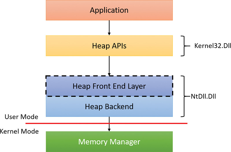
For user-mode heaps only, a front-end heap layer can exist on top of the core functionality. Windows supports one optional front end layer, the LFH, described in the upcoming section “The low-fragmentation heap.”
Heap synchronization
The heap manager supports concurrent access from multiple threads by default. However, if a process is single threaded or uses an external mechanism for synchronization, it can tell the heap manager to avoid the overhead of synchronization by specifying the HEAP_NO_SERIALIZE flag either at heap creation or on a per-allocation basis. If heap synchronization is enabled, there is one lock per heap that protects all internal heap structures.
A process can also lock the entire heap and prevent other threads from performing heap operations for operations that would require consistent states across multiple heap calls. For instance, enumerating the heap blocks in a heap with the Windows function HeapWalk requires locking the heap if multiple threads can perform heap operations simultaneously. Locking and unlocking a heap can be done with the HeapLock and HeapUnlock functions, respectively.
The low-fragmentation heap
Many applications running in Windows have relatively small heap memory usage—usually less than 1 MB. For this class of applications, the heap manager’s best-fit policy helps keep a low memory footprint for each process. However, this strategy does not scale for large processes and multiprocessor machines. In these cases, memory available for heap usage might be reduced due to heap fragmentation. Performance can suffer in scenarios where only certain sizes are often used concurrently from different threads scheduled to run on different processors. This happens because several processors need to modify the same memory location (for example, the head of the look-aside list for that particular size) at the same time, thus causing significant contention for the corresponding cache line.
The LFH avoids fragmentation by managing allocated blocks in predetermined different block-size ranges called buckets. When a process allocates memory from the heap, the LFH chooses the bucket that maps to the smallest block large enough to hold the required size. (The smallest block is 8 bytes.) The first bucket is used for allocations between 1 and 8 bytes, the second for allocations between 9 and 16 bytes, and so on, until the 32nd bucket, which is used for allocations between 249 and 256 bytes, followed by the 33rd bucket, which is used for allocations between 257 and 272 bytes, and so on. Finally, the 128th bucket, which is the last, is used for allocations between 15,873 and 16,384 bytes. (This is known as a binary buddy system.) If the allocation is larger than 16,384 bytes, the LFH simply forwards it to the underlying heap back end. Table 5-7 summarizes the different buckets, their granularity, and the range of sizes they map to.
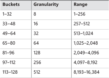
The LFH addresses these issues by using the core heap manager and look-aside lists. The Windows heap manager implements an automatic tuning algorithm that can enable the LFH by default under certain conditions, such as lock contention or the presence of popular size allocations that have shown better performance with the LFH enabled. For large heaps, a significant percentage of allocations is frequently grouped in a relatively small number of buckets of certain sizes. The allocation strategy used by LFH is to optimize the usage for these patterns by efficiently handling same-size blocks.
To address scalability, the LFH expands the frequently accessed internal structures to a number of slots that is two times larger than the current number of processors on the machine. The assignment of threads to these slots is done by an LFH component called the affinity manager. Initially, the LFH starts using the first slot for heap allocations; however, if a contention is detected when accessing some internal data, the LFH switches the current thread to use a different slot. Further contentions will spread threads on more slots. These slots are controlled for each size bucket to improve locality and minimize the overall memory consumption.
Even if the LFH is enabled as a front-end heap, the less frequent allocation sizes may continue to use the core heap functions to allocate memory, while the most popular allocation classes will be performed
from the LFH. Once the LFH is enabled for a specific heap, it cannot be disabled. The HeapSetInfor-mation API with the HeapCompatibilityInformation class that was able to remove the LFH layer in Windows 7 and earlier versions of Windows is now ignored.
The segment heap
Figure 5-9 shows the architecture of the segment heap, introduced in Windows 10.
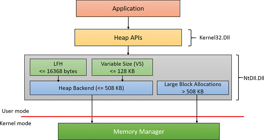
The actual layer that manages an allocation depends on the allocation size as follows:
![]() For small sizes (less than or equal to 16,368 bytes), the LFH allocator is used, but only if the size is determined to be a common one. This is a similar logic to the LFH front layer of the NT heap. If the LFH has not kicked in yet, the variable size (VS) allocator will be used instead.
For small sizes (less than or equal to 16,368 bytes), the LFH allocator is used, but only if the size is determined to be a common one. This is a similar logic to the LFH front layer of the NT heap. If the LFH has not kicked in yet, the variable size (VS) allocator will be used instead.
![]() For sizes less than or equal to 128 KB (and not serviced by the LFH), the VS allocator is used. Both VS and LFH allocators use the back end to create the required heap sub-segments as necessary.
For sizes less than or equal to 128 KB (and not serviced by the LFH), the VS allocator is used. Both VS and LFH allocators use the back end to create the required heap sub-segments as necessary.
![]() Allocations larger than 128 KB and less than or equal to 508 KB are serviced directly by the heap back end.
Allocations larger than 128 KB and less than or equal to 508 KB are serviced directly by the heap back end.
![]() Allocations larger than 508 KB are serviced by calling the memory manager directly (
Allocations larger than 508 KB are serviced by calling the memory manager directly (VirtualAlloc) since these are so large that using the default 64 KB allocation granularity (and rounding to the nearest page size) is deemed good enough.
Here is a quick comparison of the two heap implementations:
![]() In some scenarios, the segment heap may be somewhat slower than the NT heap. However, it’s likely that future Windows versions would make it on par with the NT heap.
In some scenarios, the segment heap may be somewhat slower than the NT heap. However, it’s likely that future Windows versions would make it on par with the NT heap.
![]() The segment heap has a lower memory footprint for its metadata, making it better suited for low-memory devices such as phones.
The segment heap has a lower memory footprint for its metadata, making it better suited for low-memory devices such as phones.
![]() The segment heap’s metadata is separated from the actual data, while the NT heap’s metadata is interspersed with the data itself. This makes the segment heap more secure, as it’s more difficult to get to the metadata of an allocation given just a block address.
The segment heap’s metadata is separated from the actual data, while the NT heap’s metadata is interspersed with the data itself. This makes the segment heap more secure, as it’s more difficult to get to the metadata of an allocation given just a block address.
![]() The segment heap can be used only for a growable heap. It cannot be used with a user-supplied memory mapped file. If such a segment heap creation is attempted, an NT heap is created instead.
The segment heap can be used only for a growable heap. It cannot be used with a user-supplied memory mapped file. If such a segment heap creation is attempted, an NT heap is created instead.
![]() Both heaps support LFH-type allocations, but their internal implementation is completely different. The segment heap has a more efficient implementation in terms of memory consumption and performance.
Both heaps support LFH-type allocations, but their internal implementation is completely different. The segment heap has a more efficient implementation in terms of memory consumption and performance.
As mentioned, UWP apps use segment heaps by default. This is mainly because of their lower memory footprint, which is suitable for low-memory devices. It’s also used with certain system processes based on executable name: csrss.exe, lsass.exe, runtimebroker.exe, services.exe, smss.exe, and svchost.exe.
The segment heap is not the default heap for desktop apps because there are some compatibility concerns that may affect existing applications. It’s likely that in future versions, however, it will become the default. To enable or disable the segment heap for a specific executable, you can set an Image File Execution Options value named FrontEndHeapDebugOptions (DWORD):
![]() Bit 2 (4) to disable segment heap
Bit 2 (4) to disable segment heap
![]() Bit 3 (8) to enable segment heap
Bit 3 (8) to enable segment heap
You can also globally enable or disable the segment heap by adding a value named Enabled (DWORD) to the HKLM\ SYSTEM\CurrentControlSet\Control\Session Manager\Segment Heap registry key. A zero value disables the segment heap and a non-zero value enables it.
Heap security features
As the heap manager has evolved, it has taken an increased role in early detection of heap usage errors and in mitigating effects of potential heap-based exploits. These measures exist to lessen the security effect of potential vulnerabilities in applications. Both the NT-heap and the segment-heap implementations have multiple mechanisms that reduce the likelihood of memory exploitation.
The metadata used by the heaps for internal management is packed with a high degree of randomization to make it difficult for an attempted exploit to patch the internal structures to prevent crashes or conceal the attack attempt. These blocks are also subject to an integrity-check mechanism on the header to detect simple corruptions such as buffer overruns. Finally, the heap uses a small degree of randomization of the base address or handle. By using the HeapSetInformation API with the Heap-EnableTerminationOnCorruption class, processes can opt in for an automatic termination in case of detected inconsistencies to avoid executing unknown code.
As an effect of block metadata randomization, using the debugger to simply dump a block header as an area of memory is not that useful. For example, the size of the block and whether it is busy are not easy to spot from a regular dump. The same applies to LFH blocks. They have a different type of metadata stored in the header, also partially randomized. To dump these details, the !heap –i command in the debugger does all the work to retrieve the metadata fields from a block, also flagging checksum or free-list inconsistencies if they exist. The command works for both LFH and regular heap blocks. The total size of the blocks, the user-requested size, the segment owning the block, and the header partial checksum are available in the output, as shown in the following sample. Because the randomization algorithm uses the heap granularity, the !heap –i command should be used only in the proper context of the heap containing the block. In the example, the heap handle is 0x001a0000. If the current heap context were different, the decoding of the header would be incorrect. To set the proper context, the same !heap –i command with the heap handle as an argument must be executed first.
0:004> !heap -i 000001f72a5e0000
Heap context set to the heap 0x000001f72a5e0000
0:004> !heap -i 000001f72a5eb180
Detailed information for block entry 000001f72a5eb180
Assumed heap : 0x000001f72a5e0000 (Use !heap -i NewHeapHandle to change)
Header content : 0x2FB544DC 0x1000021F (decoded : 0x7F01007E 0x10000048)
Owning segment : 0x000001f72a5e0000 (offset 0)
Block flags : 0x1 (busy )
Total block size : 0x7e units (0x7e0 bytes)
Requested size : 0x7d0 bytes (unused 0x10 bytes)
Previous block size: 0x48 units (0x480 bytes)
Block CRC : OK - 0x7f
Previous block : 0x000001f72a5ead00
Next block : 0x000001f72a5eb960
Segment heap-specific security features
The segment heap implementation uses many security mechanisms to make it harder to corrupt memory or to allow code injection by an attacker. Here are a few of them:
![]() Fail fast on linked list node corruption The segment heap uses linked lists to track segments and sub-segments. As with the NT heap, checks are added in the list node insertion and removal to prevent arbitrary memory writes due to corrupted list nodes. If a corrupted node is detected, the process is terminated via a call to
Fail fast on linked list node corruption The segment heap uses linked lists to track segments and sub-segments. As with the NT heap, checks are added in the list node insertion and removal to prevent arbitrary memory writes due to corrupted list nodes. If a corrupted node is detected, the process is terminated via a call to RtlFailFast.
![]() Fail fast on red-black (RB) tree node corruption The segment heap uses RB trees to track free back-end and VS allocations. Node insertion and deletion functions validate the nodes involved or, if corrupted, invoke the fail-fast mechanism.
Fail fast on red-black (RB) tree node corruption The segment heap uses RB trees to track free back-end and VS allocations. Node insertion and deletion functions validate the nodes involved or, if corrupted, invoke the fail-fast mechanism.
![]() Function pointer decoding Some aspects of the segment heap allow for callbacks (in
Function pointer decoding Some aspects of the segment heap allow for callbacks (in VsContext and LfhContext structures, part of the _SEGMENT_HEAP structure). An attacker can override these callbacks to point to his or her own code. However, the function pointers are encoded by using a XOR function with an internal random heap key and the context address, both of which cannot be guessed in advance.
![]() Guard pages When LFH and VS sub-segments and large blocks are allocated, a guard page is added at the end. This helps to detect overflows and corruption of adjacent data. See the section “Stacks” later in this chapter for more information on guard pages.
Guard pages When LFH and VS sub-segments and large blocks are allocated, a guard page is added at the end. This helps to detect overflows and corruption of adjacent data. See the section “Stacks” later in this chapter for more information on guard pages.
Heap debugging features
The heap manager includes several features to help detect bugs by using the following heap settings:
![]() Enable tail checking The end of each block carries a signature that is checked when the block is released. If a buffer overrun destroys the signature entirely or partially, the heap will report this error.
Enable tail checking The end of each block carries a signature that is checked when the block is released. If a buffer overrun destroys the signature entirely or partially, the heap will report this error.
![]() Enable free checking A free block is filled with a pattern that is checked at various points when the heap manager needs to access the block, such as at removal from the free list to satisfy an allocate request. If the process continues to write to the block after freeing it, the heap manager will detect changes in the pattern and the error will be reported.
Enable free checking A free block is filled with a pattern that is checked at various points when the heap manager needs to access the block, such as at removal from the free list to satisfy an allocate request. If the process continues to write to the block after freeing it, the heap manager will detect changes in the pattern and the error will be reported.
![]() Parameter checking This function consists of extensive checking of the parameters passed to the heap functions.
Parameter checking This function consists of extensive checking of the parameters passed to the heap functions.
![]() Heap validation The entire heap is validated at each heap call.
Heap validation The entire heap is validated at each heap call.
![]() Heap tagging and stack traces support This function supports the specification of tags for allocation and/or captures user-mode stack traces for the heap calls to help narrow the possible causes of a heap error.
Heap tagging and stack traces support This function supports the specification of tags for allocation and/or captures user-mode stack traces for the heap calls to help narrow the possible causes of a heap error.
The first three options are enabled by default if the loader detects that a process is started under the control of a debugger. (A debugger can override this behavior and turn off these features.) You can specify the heap debugging features for an executable image by setting various debugging flags in the image header using the Gflags tool. (See the next experiment and the section “Windows global flags” in Chapter 8 in Part 2.) Alternatively, you can enable heap debugging options using the !heap command in the standard Windows debuggers. (See the debugger help for more information.)
Enabling heap-debugging options affects all heaps in the process. Also, if any of the heap-debugging options are enabled, the LFH will be disabled automatically and the core heap will be used (with the required debugging options enabled). The LFH is also not used for heaps that are not expandable (because of the extra overhead added to the existing heap structures) or for heaps that do not allow serialization.
Pageheap
Because the tail and free checking options described in the preceding sections might discover corruptions that occurred well before the problem was detected, an additional heap debugging capability, called pageheap, is provided. Pageheap directs all or part of the heap calls to a different heap manager. You can enable pageheap using the Gflags tool (part of the Debugging Tools for Windows). When enabled, the heap manager places allocations at the end of pages and reserves the page that immediately follows. Because reserved pages are not accessible, any buffer overruns that occur will cause an access violation, making it easier to detect the offending code. Optionally, pageheap allows for the placement of blocks at the beginning of the pages, with the preceding page reserved, to detect buffer underrun problems (a rare occurrence). Pageheap also can protect freed pages against any access to detect references to heap blocks after they have been freed.
Note that using the pageheap can cause you to run out of address space (in 32-bit processes) because of the significant overhead added for small allocations. Also, performance can suffer due to the increase of references to demand zero pages, loss of locality, and additional overhead caused by frequent calls to validate heap structures. A process can reduce the impact by specifying that the pageheap be used only for blocks of certain sizes, address ranges, and/or originating DLLs.
In this experiment, you’ll turn on pageheap for Notepad.exe and see its effects.
1. Run Notepad.exe.
2. Open Task Manager, click to the Details tab, and add the Commit Size column to the display.
3. Notice the commit size of the notepad instance you just launched.
4. Run Gflags.exe, located in the folder where Debugging Tools for Windows is installed (requires elevation).
5. Click the Image File tab.
6. In the Image text box, type notepad.exe. Then press the Tab key. The various check boxes should be selected.
7. Select the Enable Page Heap check box. The dialog box should look like this:
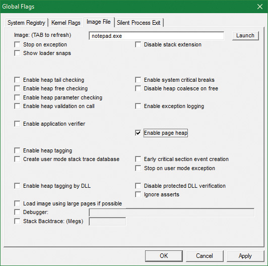
8. Click Apply.
9. Run another instance of Notepad. (Don’t close the first one.)
10. In Task Manager, compare the commit size of both notepad instances. Notice that the second instance has a much larger commit size even though both are empty notepad processes. This is due to the extra allocations that pageheap provides. Here’s a screenshot from 32-bit Windows 10:
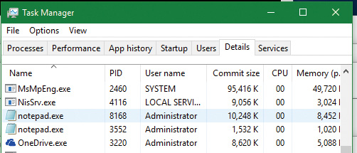
11. To get a better sense of the extra memory allocated, use the VMMap Sysinternals tool. While the notepad processes are still running, open VMMap.exe and select the notepad instance that is using pageheap:
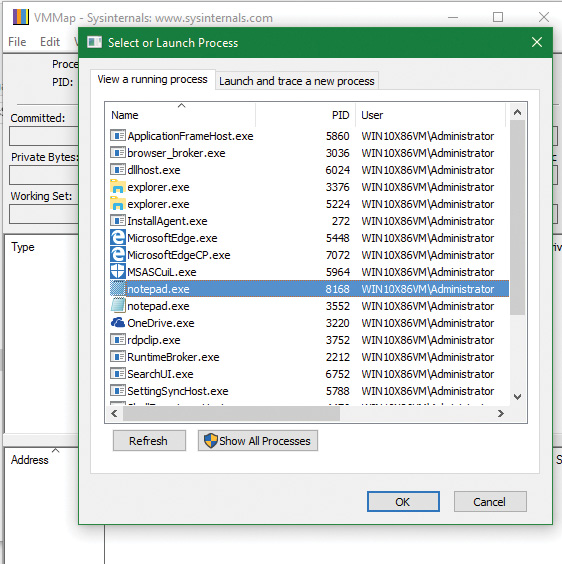
12. Open another instance of VMMap and select the other notepad instance. Place the windows side by side to see both:
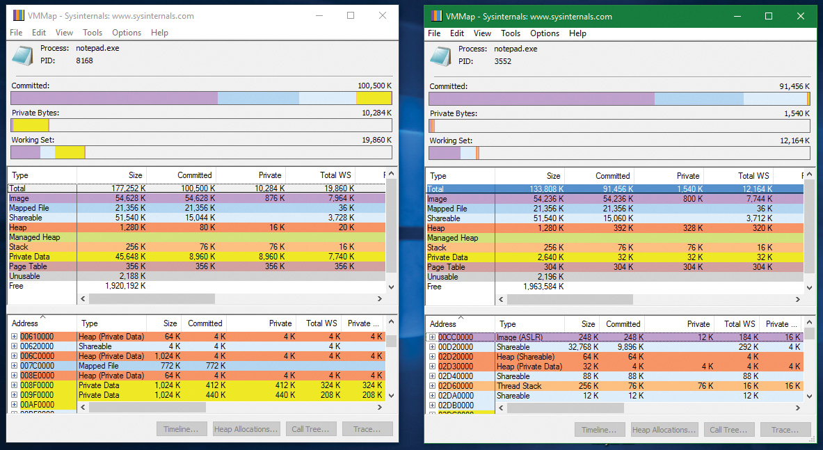
13. Notice that the difference in the commit size is clearly visible in the Private Data (yellow) part.
14. Click the Private Data line in the middle display on both VMMap instances to see its parts in the bottom display (sorted by size in the screenshot):
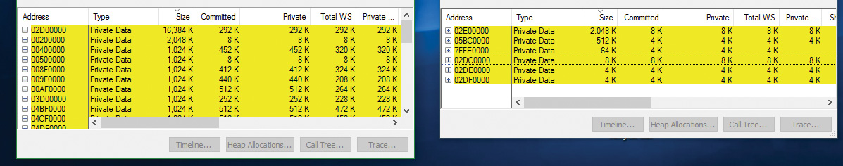
15. The left screenshot (notepad with pageheap) clearly consumes more memory. Open one of the 1,024 KB chunks. You should see something like this:
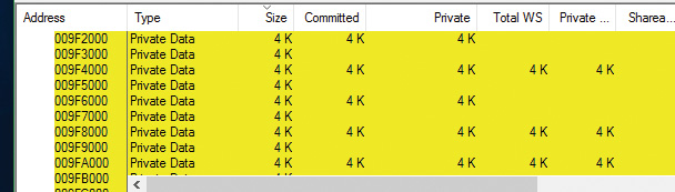
16. You can clearly see the reserved pages between committed pages that help catch buffer overruns and underruns courtesy of pageheap. Uncheck the Enable Page Heap option in Gflags and click Apply so future instances of notepad will run without pageheap.
Fault-tolerant heap
Microsoft has identified the corruption of heap metadata as one of the most common causes of application failures. Windows includes a feature called the fault-tolerant heap (FTH) to mitigate these problems and to provide better problem-solving resources to application developers. The FTH is implemented in two primary components:
![]() The detection component (FTH server)
The detection component (FTH server)
![]() The mitigation component (FTH client)
The mitigation component (FTH client)
The detection component is a DLL called Fthsvc.dll that is loaded by the Windows Security Center service (Wscsvc.dll), which in turn runs in one of the shared service processes under the local service account. It is notified of application crashes by the Windows Error Reporting (WER) service.
Suppose an application crashes in Ntdll.dll with an error status indicating either an access violation or a heap-corruption exception. If it is not already on the FTH service’s list of watched applications, the service creates a “ticket” for the application to hold the FTH data. If the application subsequently crashes more than four times in an hour, the FTH service configures the application to use the FTH client in the future.
The FTH client is an application-compatibility shim. This mechanism has been used since Windows XP to allow applications that depend on a particular behavior of older Windows systems to run on later systems. In this case, the shim mechanism intercepts the calls to the heap routines and redirects them to its own code. The FTH code implements numerous mitigations that attempt to allow the application to survive despite various heap-related errors.
For example, to protect against small buffer overrun errors, the FTH adds 8 bytes of padding and an FTH reserved area to each allocation. To address a common scenario in which a block of heap is accessed after it is freed, HeapFree calls are implemented only after a delay. “Freed” blocks are put on a list, and freed only when the total size of the blocks on the list exceeds 4 MB. Attempts to free regions that are not actually part of the heap, or not part of the heap identified by the heap handle argument to HeapFree, are simply ignored. In addition, no blocks are actually freed once exit or RtlExitUserProcess has been called.
The FTH server continues to monitor the failure rate of the application after the mitigations have been installed. If the failure rate does not improve, the mitigations are removed.
You can observe the activity of the fault-tolerant heap in the Event Viewer. Follow these steps:
1. Open a Run prompt and type eventvwr.msc.
2. In the left pane, choose Event Viewer, select Applications and Services Logs, choose Microsoft, select Windows, and click Fault-Tolerant-Heap.
3. Click the Operational log.
4. The FTH may be disabled completely in the registry. in the HKLM\Software\Microsoft\FTH key, set the Enabled value to 0.
That same key contains the various FTH settings, such as the delay mentioned earlier and an exclusion list of executables (which includes by default system processes such as smss.exe, csrss.exe, wininit.exe, services.exe, winlogon.exe and taskhost.exe). A rule list is also included (RuleList value), which lists the modules and exception type (and some flags) to watch for in order for FTH to kick in. By default, a single rule is listed, indicating heap problems in Ntdll.dll of type STATUS_ACCESS_VIOLATION (0xc0000005).
The FTH does not normally operate on services, and it is disabled on Windows server systems for performance reasons. A system administrator can manually apply the shim to an application or service executable by using the Application Compatibility Toolkit.
Virtual address space layouts
This section describes the components in the user and system address space, followed by the specific layouts on 32-bit (x86 and ARM) and 64-bit (x64) systems. This information will help you to understand the limits on process and system virtual memory on these platforms.
Three main types of data are mapped into the virtual address space in Windows:
![]() Per-process private code and data As explained in Chapter 1, each process has a private address space that cannot be accessed by other processes. That is, a virtual address is always evaluated in the context of the current process and cannot refer to an address defined by any other process. Threads within the process can therefore never access virtual addresses outside this private address space. Even shared memory is not an exception to this rule, because shared memory regions are mapped into each participating process, and so are accessed by each process using per-process addresses. Similarly, the cross-process memory functions (
Per-process private code and data As explained in Chapter 1, each process has a private address space that cannot be accessed by other processes. That is, a virtual address is always evaluated in the context of the current process and cannot refer to an address defined by any other process. Threads within the process can therefore never access virtual addresses outside this private address space. Even shared memory is not an exception to this rule, because shared memory regions are mapped into each participating process, and so are accessed by each process using per-process addresses. Similarly, the cross-process memory functions (Read-ProcessMemory and WriteProcessMemory) operate by running kernel-mode code in the context of the target process. The process virtual address space, called page tables, is described in the “Address translation” section. Each process has its own set of page tables. They are stored in kernel-mode-only accessible pages so that user-mode threads in a process cannot modify their own address space layout.
![]() Session-wide code and data Session space contains information that is common to each session. (For a description of sessions, see Chapter 2.) A session consists of the processes and other system objects such as the window station, desktops, and windows that represent a single user’s logon session. Each session has a session-specific paged pool area used by the kernel-mode portion of the Windows subsystem (Win32k.sys) to allocate session-private GUI data structures. In addition, each session has its own copy of the Windows subsystem process (Csrss.exe) and logon process (Winlogon.exe). The Session Manager process (Smss.exe) is responsible for creating new sessions, which includes loading a session-private copy of Win32k.sys, creating the session-private object manager namespace (see Chapter 8 in Part 2 for more details on the object manager), and creating the session-specific instances of the Csrss.exe and Winlogon.exe processes. To virtualize sessions, all session-wide data structures are mapped into a region of system space called session space. When a process is created, this range of addresses is mapped to the pages associated with the session that the process belongs to.
Session-wide code and data Session space contains information that is common to each session. (For a description of sessions, see Chapter 2.) A session consists of the processes and other system objects such as the window station, desktops, and windows that represent a single user’s logon session. Each session has a session-specific paged pool area used by the kernel-mode portion of the Windows subsystem (Win32k.sys) to allocate session-private GUI data structures. In addition, each session has its own copy of the Windows subsystem process (Csrss.exe) and logon process (Winlogon.exe). The Session Manager process (Smss.exe) is responsible for creating new sessions, which includes loading a session-private copy of Win32k.sys, creating the session-private object manager namespace (see Chapter 8 in Part 2 for more details on the object manager), and creating the session-specific instances of the Csrss.exe and Winlogon.exe processes. To virtualize sessions, all session-wide data structures are mapped into a region of system space called session space. When a process is created, this range of addresses is mapped to the pages associated with the session that the process belongs to.
![]() System-wide code and data System space contains global operating system code and data structures visible by kernel-mode code regardless of which process is currently executing. System space consists of the following components:
System-wide code and data System space contains global operating system code and data structures visible by kernel-mode code regardless of which process is currently executing. System space consists of the following components:
• System code This contains the OS image, HAL, and device drivers used to boot the system.
• Nonpaged pool This is the non-pageable system memory heap.
• Paged pool This is the pageable system memory heap.
• System cache This is virtual address space used to map files open in the system cache. (See Chapter 11, “Startup and shutdown,” in Part 2 for detailed information.)
• System page table entries (PTEs) This is the pool of system PTEs used to map system pages such as I/O space, kernel stacks, and memory descriptor lists. You can see how many system PTEs are available by using Performance Monitor to examine the value of the Memory: Free System Page Table Entries counter.
• System working set lists These are the working set list data structures that describe the three system working sets: system cache, paged pool, and system PTEs.
• System mapped views This is used to map Win32k.sys, the loadable kernel-mode part of the Windows subsystem, as well as kernel-mode graphics drivers it uses. (See Chapter 2 for more information on Win32k.sys.)
• Hyperspace This is a special region used to map the process working set list and other per-process data that doesn’t need to be accessible in arbitrary process context. Hyperspace is also used to temporarily map physical pages into the system space. One example of this is invalidating page table entries in page tables of processes other than the current one, such as when a page is removed from the standby list.
• Crash dump information This is reserved to record information about the state of a system crash.
• HAL usage This is system memory reserved for HAL-specific structures.
Now that we’ve described the basic components of the virtual address space in Windows, let’s examine the specific layout on the x86, ARM, and x64 platforms.
x86 address space layouts
By default, each user process on 32-bit versions of Windows has a 2 GB private address space. (The operating system takes the remaining 2 GB.) However, for x86, the system can be configured with the increaseuserva BCD boot option to permit user address spaces up to 3 GB. Two possible address space layouts are shown in Figure 5-10.
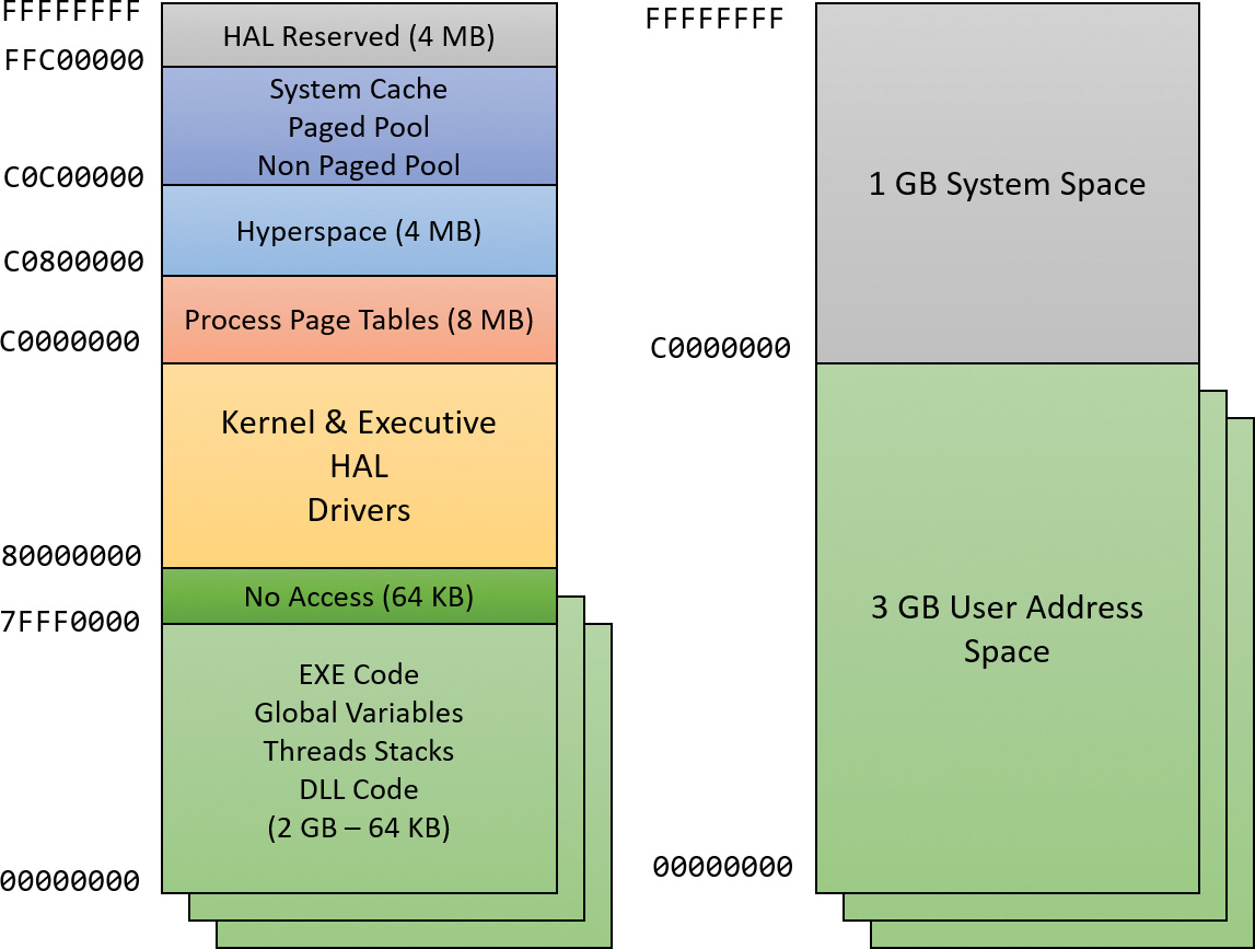
The ability of a 32-bit process to grow beyond 2 GB was added to accommodate the need for 32-bit applications to keep more data in memory than could be done with a 2 GB address space. Of course, 64-bit systems provide a much larger address space.
For a process to grow beyond 2 GB of address space, the image file must have the IMAGE_FILE_LARGE_ADDRESS_AWARE flag set in the image header (in addition to the global increaseuserva setting). Otherwise, Windows reserves the additional address space for that process so that the application won’t see virtual addresses greater than 0x7FFFFFFF. Access to the additional virtual memory is opt-in because some applications assume they’ll be given at most 2 GB of the address space. Because the high bit of a pointer referencing an address below 2 GB is always zero (31 bits are needed to reference a 2 GB address space), these applications would use the high bit in their pointers as a flag for their own data—clearing it, of course, before referencing the data. If they ran with a 3 GB address space, they would inadvertently truncate pointers that have values greater than 2 GB, causing program errors, including possible data corruption. You set this flag by specifying the /LARGEADDRESSAWARE linker flag when building the executable. Alternatively, use the Property page in Visual Studio (choose Linker, select System, and click Enable Large Addresses). You can add the flag to an executable image even without building (no source code required) by using a tool such as Editbin.exe (part of the Windows SDK tools), assuming the file is not signed. This flag has no effect when running the application on a system with a 2 GB user address space.
Several system images are marked as large address space aware so that they can take advantage of systems running with large process address spaces. These include the following:
![]() Lsass.exe The Local Security Authority Subsystem
Lsass.exe The Local Security Authority Subsystem
![]() Inetinfo.exe Internet Information Server
Inetinfo.exe Internet Information Server
![]() Chkdsk.exe The Check Disk utility
Chkdsk.exe The Check Disk utility
![]() Dllhst3g.exe A special version of Dllhost.exe (for COM+ applications)
Dllhst3g.exe A special version of Dllhost.exe (for COM+ applications)
Finally, memory allocations using VirtualAlloc, VirtualAllocEx, and VirtualAllocExNuma start with low virtual addresses and grow higher by default. Unless a process allocates a lot of memory or has a very fragmented virtual address space, it will never get back very high virtual addresses. Therefore, for testing purposes, you can force memory allocations to start from high addresses by using the MEM_TOP_DOWN flag to the VirtualAlloc* functions or by adding a DWORD registry value named AllocationPreference to the HKLM\SYSTEM\CurrentControlSet\Control\Session Manager\Memory Management key and setting its value to 0x100000.
The following output shows runs of the TestLimit utility (shown in previous experiments) leaking memory on a 32-bit Windows machine booted without the increaseuserva option:
Testlimit.exe -r
Testlimit v5.24 - test Windows limits
Copyright (C) 2012-2015 Mark Russinovich
Sysinternals - www.sysinternals.com
Process ID: 5500
Reserving private bytes (MB)...
Leaked 1978 MB of reserved memory (1940 MB total leaked). Lasterror: 8
The process managed to reserve close to the 2 GB limit (but not quite). The process address space has the EXE code and various DLLs mapped, so naturally it’s not possible in a normal process to reserve the entire address space.
On that same system, you can switch to a 3 GB address space by running the following command from an administrative command window:
C:\WINDOWS\system32>bcdedit /set increaseuserva 3072
The operation completed successfully.
Notice that the command allows you to specify any number (in MB) between 2,048 (the 2 GB default) to 3,072 (the 3 GB maximum). After you restart the system so that the setting can take effect, running TestLimit again produces the following:
Testlimit.exe -r
Testlimit v5.24 - test Windows limits
Copyright (C) 2012-2015 Mark Russinovich
Sysinternals - www.sysinternals.com
Process ID: 2308
Reserving private bytes (MB)...
Leaked 2999 MB of reserved memory (2999 MB total leaked). Lasterror: 8
TestLimit was able to leak close to 3 GB, as expected. This is only possible because TestLimit was linked with /LARGEADDRESSAWARE. Had it not been, the results would have been essentially the same as on the system booted without increaseuserva.
![]() Note
Note
To revert a system to the normal 2 GB address space per process, run the bcdedit /deletevalue increaseuserva command.
x86 system address space layout
The 32-bit versions of Windows implement a dynamic system address space layout by using a virtual address allocator. (We’ll describe this functionality later in this section.) There are still a few specifically reserved areas, as shown in Figure 5-10. However, many kernel-mode structures use dynamic address space allocation. These structures are therefore not necessarily virtually contiguous with themselves. Each can easily exist in several disjointed pieces in various areas of system address space. The uses of system address space that are allocated in this way include the following:
![]() Non-paged pool
Non-paged pool
![]() Paged pool
Paged pool
![]() Special pool
Special pool
![]() System mapped views
System mapped views
![]() File system cache
File system cache
![]() PFN database
PFN database
![]() Session space
Session space
x86 session space
For systems with multiple sessions (which is almost always the case, as session 0 is used by system processes and services, while session 1 is used for the first logged on user), the code and data unique to each session are mapped into system address space but shared by the processes in that session. Figure 5-11 shows the general layout of session space. The sizes of the components of session space, just like the rest of kernel system address space, are dynamically configured and resized by the memory manager on demand.
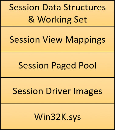
System page table entries
System page table entries (PTEs) are used to dynamically map system pages such as I/O space, kernel stacks, and the mapping for memory descriptor lists (MDLs, discussed to some extent in Chapter 6). System PTEs aren’t an infinite resource. On 32-bit Windows, the number of available system PTEs is such that the system can theoretically describe 2 GB of contiguous system virtual address space. On Windows 10 64 bit and Server 2016, system PTEs can describe up to 16 TB of contiguous virtual address space.
ARM address space layout
As shown in Figure 5-12, the ARM address space layout is nearly identical to the x86 address space. The memory manager treats ARM-based systems exactly as x86 systems in terms of pure memory management. The differences are at the address translation layer, described in the section “Address translation” later in this chapter.
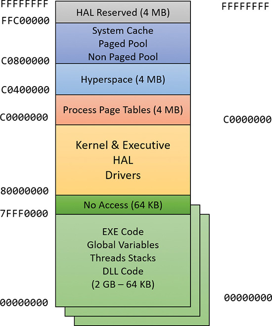
64-bit address space layout
The theoretical 64-bit virtual address space is 16 exabytes (EB), or 18,446,744,073,709,551,616 bytes. Current processor limitations allow for 48 address lines only, limiting the possible address space to 256 TB (2 to the 48th power). The address space is divided in half, where the lower 128 TB are available as private user processes and the upper 128 TB are system space. System space is divided into several different-sized regions (Windows 10 and Server 2016), as shown in Figure 5-13. Clearly, 64 bits provides a tremendous leap in terms of address space sizes as opposed to 32 bit. The actual starts of various kernel sections are not necessarily those shown, as ASLR is in effect in kernel space in the latest versions of Windows.
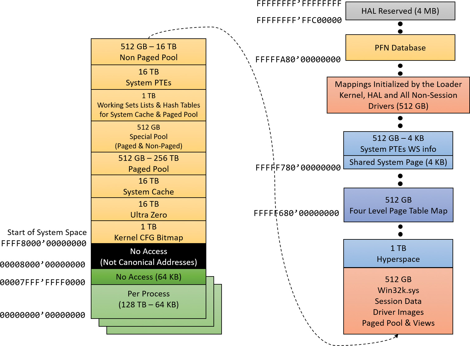
![]() Note
Note
Windows 8 and Server 2012 are limited to 16 TB of address space. This is because of Windows implementation limitations, described in Chapter 10 of the sixth edition of Windows Internals Part 2. Of these, 8 TB is per process and the other 8 TB is used for system space.
Thirty-two–bit images that are large address space aware receive an extra benefit while running on 64-bit Windows (under Wow64). Such an image will actually receive all 4 GB of user address space available. After all, if the image can support 3 GB pointers, 4 GB pointers should not be any different, because unlike the switch from 2 GB to 3 GB, there are no additional bits involved. The following output shows TestLimit running as a 32-bit application, reserving address space on a 64-bit Windows machine.
C:\Tools\Sysinternals>Testlimit.exe -r
Testlimit v5.24 - test Windows limits
Copyright (C) 2012-2015 Mark Russinovich
Sysinternals - www.sysinternals.com
Process ID: 264
Reserving private bytes (MB)...
Leaked 4008 MB of reserved memory (4008 MB total leaked). Lasterror: 8
Not enough storage is available to process this command.
These results depend on TestLimit having been linked with the /LARGEADDRESSAWARE option. Had it not been, the results would have been about 2 GB for each. Sixty-four–bit applications linked without /LARGEADDRESSAWARE are constrained to the first 2 GB of the process virtual address space, just like 32-bit applications. (This flag is set by default in Visual Studio for 64-bit builds.)
x64 virtual addressing limitations
As discussed, 64 bits of virtual address space allow for a possible maximum of 16 EB of virtual memory —a notable improvement over the 4 GB offered by 32-bit addressing. Obviously, neither today’s computers nor tomorrow’s are even close to requiring support for that much memory.
Accordingly, to simplify chip architecture and avoid unnecessary overhead—particularly in address translation (described later)—AMD’s and Intel’s current x64 processors implement only 256 TB of virtual address space. That is, only the low-order 48 bits of a 64-bit virtual address are implemented. However, virtual addresses are still 64 bits wide, occupying 8 bytes in registers or when stored in memory. The high-order 16 bits (bits 48 through 63) must be set to the same value as the highest-order implemented bit (bit 47), in a manner similar to sign extension in two’s complement arithmetic. An address that conforms to this rule is said to be a canonical address.
Under these rules, the bottom half of the address space starts at 0x0000000000000000 as expected, but ends at 0x00007FFFFFFFFFFF. The top half of the address space starts at 0xFFFF800000000000 and ends at 0xFFFFFFFFFFFFFFFF. Each canonical portion is 128 TB. As newer processors implement more of the address bits, the lower half of memory will expand upward toward 0x7FFFFFFFFFFFFFFF, while the upper half will expand downward toward 0x8000000000000000.
Comments
Post a Comment