Chapter 3. Processes and jobs
Chapter 3. Processes and jobs
In this chapter, we’ll explain the data structures and algorithms that deal with processes and jobs in Windows. First we’ll take a general look at process creation. Then we’ll examine the internal structures that make up a process. Next we’ll look at protected processes and how they differ from non-protected ones. After that we outline the steps involved in creating a process (and its initial thread). The chapter concludes with a description of jobs.
Because processes touch so many components in Windows, a number of terms and data structures (such as working sets, threads, objects and handles, system memory heaps, and so on) are referred to in this chapter but are explained in detail elsewhere in the book. To fully understand this chapter, you need to be familiar with the terms and concepts explained in Chapter 1, “Concepts and tools,” and Chapter 2, “System architecture,” such as the difference between a process and a thread, the Windows virtual address space layout, and the difference between user mode and kernel mode.
Creating a process
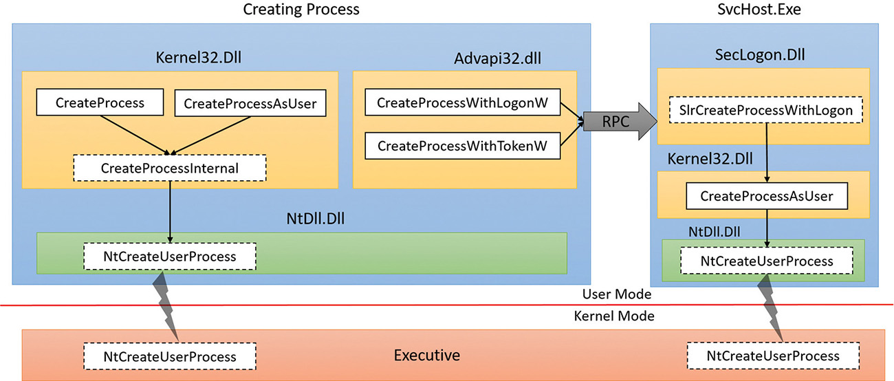
The Windows API provides several functions for creating processes. The simplest is CreateProcess, which attempts to create a process with the same access token as the creating process. If a different token is required, CreateProcessAsUser can be used, which accepts an extra argument (the first)—a handle to a token object that was already somehow obtained (for example, by calling the LogonUser function).
Other process creation functions include CreateProcessWithTokenW and CreateProcessWithLogonW (both part of advapi32.Dll). CreateProcessWithTokenW is similar to CreateProcessAsUser, but the two differ in the privileges required for the caller. (Check the Windows SDK documentation for the specifics.) CreateProcessWithLogonW is a handy shortcut to log on with a given user’s credentials and create a process with the obtained token in one stroke. Both call the Secondary Logon service (seclogon.dll, hosted in a SvcHost.Exe) by making a Remote Procedure Call (RPC) to do the actual process creation. SecLogon executes the call in its internal SlrCreateProcessWithLogon function, and if all goes well, eventually calls CreateProcessAsUser. The SecLogon service is configured by default to start manually, so the first time CreateProcessWithTokenW or CreateProcessWithLogonW is called, the service is started. If the service fails to start (for example, an administrator can configure the service to be disabled), these functions will fail. The runas command-line utility, which you may be familiar with, makes use of these functions.
Figure 3-1 shows the call graph described above.
All the above documented functions expect a proper Portable Executable (PE) file (although the EXE extension is not strictly required), batch file, or 16-bit COM application. Beyond that, they have no knowledge of how to connect files with certain extensions (for example, .txt) to an executable (for example, Notepad). This is something that is provided by the Windows Shell, in functions such as ShellExecute and ShellExecuteEx. These functions can accept any file (not just executables) and try to locate the executable to run based on the file extensions and the registry settings at HKEY_CLASSES_ ROOT. (See Chapter 9, “Management mechanisms,” in Windows Internals Part 2 for more on this.) Eventually, ShellExecute(Ex) calls CreateProcess with a proper executable and appends appropriate arguments on the command line to achieve the user’s intention (such as editing a TXT file by appending the file name to Notepad.exe).
Ultimately, all these execution paths lead to a common internal function, CreateProcessInternal, which starts the actual work of creating a user-mode Windows process. Eventually (if all goes well), CreateProcessInternal calls NtCreateUserProcess in Ntdll.dll to make the transition to kernel mode and continue the kernel-mode part of process creation in the function with the same name (NtCreateUserProcess), part of the Executive.
CreateProcess* functions arguments
It’s worthwhile to discuss the arguments to the CreateProcess* family of functions, some of which will
be referred to in the section on the flow of CreateProcess. A process created from user mode is always created with one thread within it. This is the thread that eventually will execute the main function of the executable. Here are the important arguments to the CreateProcess* functions:
![]() For
For CreateProcessAsUser and CreateProcessWithTokenW, the token handle under which the new process should execute. Similarly, for CreateProcessWithLogonW, the username, domain and password are required.
![]() The executable path and command-line arguments.
The executable path and command-line arguments.
![]() Optional security attributes applied to the new process and thread object that’s about to be created.
Optional security attributes applied to the new process and thread object that’s about to be created.
![]() A Boolean flag indicating whether all handles in the current (creating) process that are marked inheritable should be inherited (copied) to the new process. (See Chapter 8, “System mechanisms,” in Part 2 for more on handles and handle inheritance.)
A Boolean flag indicating whether all handles in the current (creating) process that are marked inheritable should be inherited (copied) to the new process. (See Chapter 8, “System mechanisms,” in Part 2 for more on handles and handle inheritance.)
![]() Various flags that affect process creation. Here are some examples. (Check the Windows SDK documentation for a complete list.)
Various flags that affect process creation. Here are some examples. (Check the Windows SDK documentation for a complete list.)
• CREATE_SUSPENDED This creates the initial thread of the new process in the suspended state. A later call to ResumeThread will cause the thread to begin execution.
• DEBUG_PROCESS The creating process is declaring itself to be a debugger, creating the new process under its control.
• EXTENDED_STARTUPINFO_PRESENT The extended STARTUPINFOEX structure is provided instead of STARTUPINFO (described below).
![]() An optional environment block for the new process (specifying environment variables). If not specified, it will be inherited from the creating process.
An optional environment block for the new process (specifying environment variables). If not specified, it will be inherited from the creating process.
![]() An optional current directory for the new process. (If not specified, it uses the one from the creating process.) The created process can later call
An optional current directory for the new process. (If not specified, it uses the one from the creating process.) The created process can later call SetCurrentDirectory to set a different one. The current directory of a process is used in various non-full path searches (such as when loading a DLL with a filename only).
![]() A
A STARTUPINFO or STARTUPINFOEX structure that provides more configuration for process creation. STARTUPINFOEX contains an additional opaque field that represents a set of process and thread attributes that are essentially an array of key/value pairs. These attributes are filled by calling UpdateProcThreadAttributes once for each attribute that’s needed. Some of these attributes are undocumented and used internally, such as when creating store apps, as described in the next section.
![]() A
A PROCESS_INFORMATION structure that is the output of a successful process creation. This structure holds the new unique process ID, the new unique thread ID, a handle to the new process and a handle to the new thread. The handles are useful for the creating process if it wants to somehow manipulate the new process or thread in some way after creation.
Creating Windows modern processes
Chapter 1 described the new types of applications available starting from Windows 8 and Windows Server 2012. The names of these apps have changed over time, but we’ll refer to them as modern apps, UWP apps, or immersive processes, to distinguish them from the classic, also known as desktop, applications.
Creating a modern application process requires more than just calling CreateProcess with the correct executable path. There are some required command-line arguments. Yet another requirement is adding an undocumented process attribute (using UpdateProcThreadAttribute) with a key named PROC_THREAD_ATTRIBUTE_PACKAGE_FULL_NAME with the value set to the full store app package name. Although this attribute is undocumented, there are other ways (from an API perspective) to execute a store app. For example, the Windows API includes a COM interface called IApplicationActivationManager that is implemented by a COM class with a CLSID named CLSID_ApplicationActivationManager. One of the methods in the interface is ActivateApplication, which can be used to launch a store app after obtaining something known as AppUserModelId from the store app full package name by calling GetPackageApplicationIds. (See the Windows SDK for more information on these APIs.)
Package names and the way a store app is typically created, from a user tapping on a modern app tile, eventually leading to CreateProcess, is discussed in Chapter 9 in Part 2.
Creating other kinds of processes
Although Windows applications launch either classic or modern applications, the Executive includes support for additional kinds of processes that must be started by bypassing the Windows API, such as native processes, minimal processes, or Pico processes. For example, we described in Chapter 2 the existence of Smss, the Session Manager, which is an example of a native image. Since it is created directly by the kernel, it obviously does not use the CreateProcess API, but instead calls directly into NtCreateUserProcess. Similarly, when Smss creates Autochk (the check disk utility) or Csrss (the Windows subsystem process), the Windows API is also not available, and NtCreateUserProcess must be used. Additionally, native processes cannot be created from Windows applications, as the CreateProcessInternal function will reject images with the native subsystem image type. To alleviate these complications, the native library, Ntdll.dll, includes an exported helper function called RtlCreateUserProcess, providing a simpler wrapper around NtCreateUserProcess.
As its name suggests, NtCreateUserProcess is used for the creation of user-mode processes. However, as we saw in Chapter 2, Windows also includes a number of kernel-mode processes, such as the System process and the Memory Compression processes (which are minimal processes), plus the possibility of Pico processes managed by a provider such as the Windows Subsystem for Linux. The creation of such processes is instead provided by the NtCreateProcessEx system call, with certain capabilities reserved solely for kernel-mode callers (such as the creation of minimal processes).
Finally, Pico providers call a helper function, which takes care of both creating the minimal process as well as initializing its Pico provider context—PspCreatePicoProcess. This function is not exported, and is only available to Pico providers through their special interface.
As we’ll see in the flow section later in this chapter, although NtCreateProcessEx and NtCreate-UserProcess are different system calls, the same internal routines are used to perform the work: PspAllocateProcess and PspInsertProcess. All the possible ways we’ve enumerated so far to create a process, and any ways you can imagine, from a WMI PowerShell cmdlet to a kernel driver, will end
up there.
Process internals
This section describes the key Windows process data structures maintained by various parts of the system and describes different ways and tools to examine this data.
Each Windows process is represented by an executive process (EPROCESS) structure. Besides containing many attributes relating to a process, an EPROCESS contains and points to a number of other related data structures. For example, each process has one or more threads, each represented by an executive thread (ETHREAD) structure. (Thread data structures are explained in Chapter 4, “Threads”.)
The EPROCESS and most of its related data structures exist in system address space. One exception is the Process Environment Block (PEB), which exists in the process (user) address space (because it contains information accessed by user-mode code). Additionally, some of the process data structures used in memory management, such as the working set list, are valid only within the context of the current process, because they are stored in process-specific system space. (See Chapter 5, “Memory management,” for more information on process address space.)
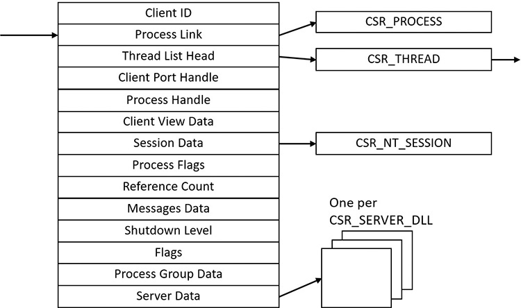
For each process that is executing a Windows program, the Windows subsystem process (Csrss) maintains a parallel structure called the CSR_PROCESS. Additionally, the kernel-mode part of the Windows subsystem (Win32k.sys) maintains a per-process data structure, W32PROCESS, which is created the first time a thread calls a Windows USER or GDI function that is implemented in kernel mode. This happens as soon as the User32.dll library is loaded. Typical functions that cause this library to be loaded are CreateWindow(Ex) and GetMessage.
Since the kernel-mode Windows subsystem makes heavy use of DirectX-based hardware accelerated graphics, the Graphics Device Interface (GDI) component infrastructure causes the DirectX Graphics Kernel (Dxgkrnl.sys) to initialize a structure of its own, DXGPROCESS. This structure contains information for DirectX objects (surfaces, shaders, etc.) and the GPGPU-related counters and policy settings for both computational and memory management–related scheduling.
Except for the idle process, every EPROCESS structure is encapsulated as a process object by the executive object manager (described in Chapter 8 in Part 2). Because processes are not named objects, they are not visible in the WinObj tool (from Sysinternals). You can, however, see the Type object called Process in the \ObjectTypes directory (in WinObj). A handle to a process provides, through use of the process-related APIs, access to some of the data in the EPROCESS structure and in some of its associated structures.
Many other drivers and system components, by registering process-creation notifications, can choose to create their own data structures to track information they store on a per-process basis. (The executive functions PsSetCreateProcessNotifyRoutine(Ex, Ex2) allow this and are documented in the WDK.) When one discusses the overhead of a process, the size of such data structures must often be taken into consideration, although it is nearly impossible to obtain an accurate number. Additionally, some of these functions allow such components to disallow, or block, the creation of processes. This provides anti-malware vendors with an architectural way to add security enhancements to the operating system, either through hash-based blacklisting or other techniques.
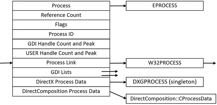
First let’s focus on the Process object. Figure 3-2 shows the key fields in an EPROCESS structure.
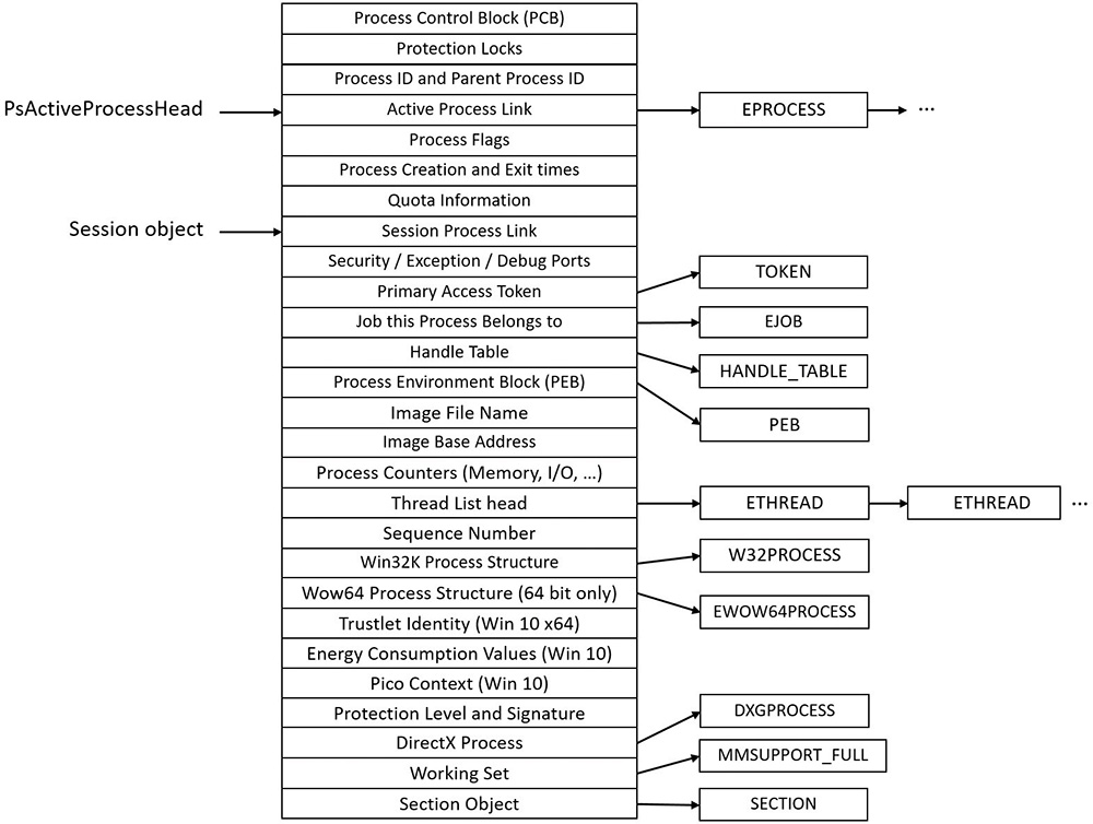
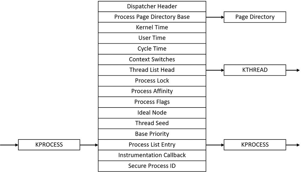
Similar to the way the kernel’s APIs and components are divided into isolated and layered modules with their own naming conventions, the data structures for a process follow a similar design. As shown in Figure 3-2, the first member of the executive process structure is called Pcb (Process Control Block). It is a structure of type KPROCESS, for kernel process. Although routines in the executive store information in the EPROCESS, the dispatcher, scheduler, and interrupt/time accounting code—being part of the operating system kernel—use the KPROCESS instead. This allows a layer of abstraction to exist between the executive’s high-level functionality and its underlying low-level implementation of certain functions, and helps prevent unwanted dependencies between the layers. Figure 3-3 shows the key fields in a KPROCESS structure.
If you’re using the latest Windows 10 SDK, the updated version of WinDbg will include an intuitive hyperlink under the PEB address, which you can click to automatically execute both the .process command and the !peb command.
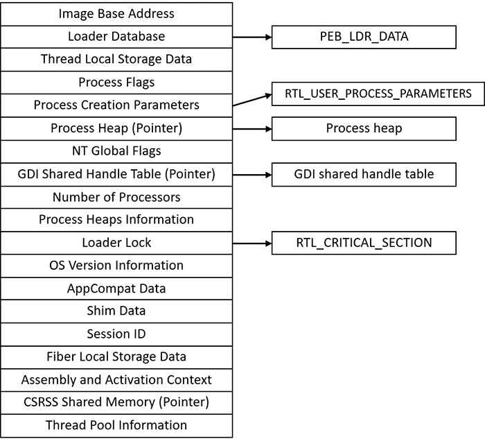
The PEB lives in the user-mode address space of the process it describes. It contains information needed by the image loader, the heap manager, and other Windows components that need to access it from user mode; it would be too expensive to expose all that information through system calls. The EPROCESS and KPROCESS structures are accessible only from kernel mode. The important fields of the PEB are illustrated in Figure 3-4 and are explained in more detail later in this chapter.
The CSR_PROCESS structure contains information about processes that is specific to the Windows subsystem (Csrss). As such, only Windows applications have a CSR_PROCESS structure associated with them (for example, Smss does not). Additionally, because each session has its own instance of the Windows subsystem, the CSR_PROCESS structures are maintained by the Csrss process within each individual session. The basic structure of the CSR_PROCESS is illustrated in Figure 3-5 and is explained in more detail later in this chapter.
The W32PROCESS structure is the final system data structure associated with processes that we’ll look at. It contains all the information that the Windows graphics and window management code in the kernel (Win32k) needs to maintain state information about GUI processes (which were defined earlier as processes that have done at least one USER/GDI system call). The basic structure of the W32PROCESS is illustrated in Figure 3-6. Unfortunately, since type information for Win32k structures is not available in public symbols, we can’t easily show you an experiment displaying this information. Either way, discussion of graphics-related data structures and concepts is beyond the scope of this book.
Protected processes
In the Windows security model, any process running with a token containing the debug privilege (such as an administrator’s account) can request any access right that it desires to any other process running on the machine. For example, it can read and write arbitrary process memory, inject code, suspend and resume threads, and query information on other processes. Tools such as Process Explorer and Task Manager need and request these access rights to provide their functionality to users.
This logical behavior (which helps ensure that administrators will always have full control of the running code on the system) clashes with the system behavior for digital rights management requirements imposed by the media industry on computer operating systems that need to support playback of advanced, high-quality digital content such as Blu-ray media. To support reliable and protected playback of such content, Windows Vista and Windows Server 2008 introduced protected processes. These processes exist alongside normal Windows processes, but they add significant constraints to the access rights that other processes on the system (even when running with administrative privileges) can request.
Protected processes can be created by any application. However, the operating system will allow a process to be protected only if the image file has been digitally signed with a special Windows Media Certificate. The Protected Media Path (PMP) in Windows makes use of protected processes to provide protection for high-value media, and developers of applications such as DVD players can make use of protected processes by using the Media Foundation (MF) API.
The Audio Device Graph process (Audiodg.exe) is a protected process because protected music content can be decoded through it. Related to this is the Media Foundation Protected Pipeline (Mfpmp.exe), which is also a protected process for similar reasons (it does not run by default). Similarly, the Windows Error Reporting (WER; discussed in Chapter 8 in Part 2) client process (Werfaultsecure.exe) can also run protected because it needs to have access to protected processes in case one of them crashes. Finally, the System process itself is protected because some of the decryption information is generated by the Ksecdd.sys driver and stored in its user-mode memory. The System process is also protected to protect the integrity of all kernel handles (because the System process’s handle table contains all the kernel handles on the system). Since other drivers may also sometimes map memory inside the user-mode address space of the System process (such as Code Integrity certificate and catalog data), it’s yet another reason for keeping the process protected.
At the kernel level, support for protected processes is twofold. First, the bulk of process creation occurs in kernel mode to avoid injection attacks. (The flow for both protected and standard process creation is described in detail in the next section.) Second, protected processes (and their extended cousin, Protected Processes Light [PPL], described in the next section) have special bits set in their EPROCESS structure that modify the behavior of security-related routines in the process manager to deny certain access rights that would normally be granted to administrators. In fact, the only access rights that are granted for protected processes are PROCESS_QUERY/SET_LIMITED_INFORMATION, PROCESS_TERMINATE and PROCESS_SUSPEND_RESUME. Certain access rights are also disabled for threads running inside protected processes. We will look at those access rights in Chapter 4 in the section “Thread internals.”
Because Process Explorer uses standard user-mode Windows APIs to query information on process internals, it is unable to perform certain operations on such processes. On the other hand, a tool like WinDbg in kernel-debugging mode, which uses kernel-mode infrastructure to obtain this information, will be able to display complete information. See the experiment in the “Thread internals” section in Chapter 4 on how Process Explorer behaves when confronted with a protected process such as Audiodg.exe.
![]() Note
Note
As mentioned in Chapter 1, to perform local kernel debugging, you must boot in debugging mode (enabled by using bcdedit /debug on or by using the Msconfig advanced boot options). This mitigates against debugger-based attacks on protected processes and the PMP. When booted in debugging mode, high-definition content playback will not work.
Limiting these access rights reliably allows the kernel to sandbox a protected process from user-mode access. On the other hand, because a protected process is indicated by a flag in the EPROCESS structure, an administrator can still load a kernel-mode driver that modifies this flag. However, this would be a violation of the PMP model and considered malicious, and such a driver would likely eventually be blocked from loading on a 64-bit system because the kernel-mode, code-signing policy prohibits the digital signing of malicious code. Additionally, kernel-mode patch protection, known as PatchGuard (described in Chapter 7), as well as the Protected Environment and Authentication Driver (Peauth.sys), will recognize and report such attempts. Even on 32-bit systems, the driver has to be recognized by PMP policy or the playback may be halted. This policy is implemented by Microsoft and not by any kernel detection. This block would require manual action from Microsoft to identify the signature as malicious and update the kernel.
Protected Process Light (PPL)
As we just saw, the original model for protected processes focused on DRM-based content. Starting with Windows 8.1 and Windows Server 2012 R2, an extension to the protected process model was introduced, called Protected Process Light (PPL).
PPLs are protected in the same sense as classic protected processes: User-mode code (even running with elevated privileges) cannot penetrate these processes by injecting threads or obtaining detailed information about loaded DLLs. However, the PPL model adds an additional dimension to the quality of being protected: attribute values. The different Signers have differing trust levels, which in turn results in certain PPLs being more, or less, protected than other PPLs.
Because DRM evolved from merely multimedia DRM to also Windows licensing DRM and Windows Store DRM, standard protected processes are now also differentiated based on the Signer value. Finally, the various recognized Signers also define which access rights are denied to lesser protected processes. For example, normally, the only access masks allowed are PROCESS_QUERY/SET_LIMITED_INFORMATION and PROCESS_SUSPEND_RESUME. PROCESS_TERMINATE is not allowed for certain PPL signers.
Table 3-1 shows the legal values for the protection flag stored in the EPROCESS structure.
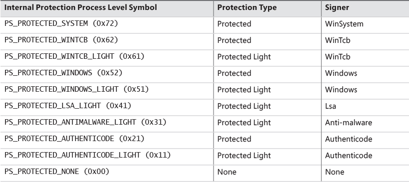
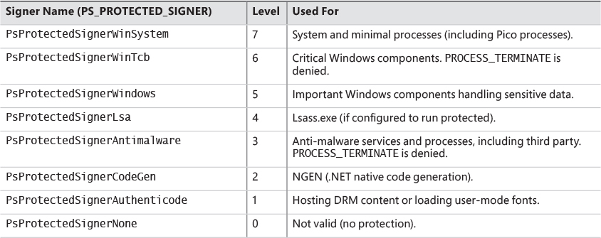
As shown in Table 3-1, there are several signers defined, from high to low power. WinSystem is the highest-priority signer and used for the System process and minimal processes such as the Memory Compression process. For user-mode processes, WinTCB (Windows Trusted Computer Base) is the highest-priority signer and leveraged to protect critical processes that the kernel has intimate knowledge of and might reduce its security boundary toward. When interpreting the power of a process, keep in mind that first, protected processes always trump PPLs, and that next, higher-value signer processes have access to lower ones, but not vice versa. Table 3-2 shows the signer levels (higher values denote the signer is more powerful) and some examples of their usage. You can also dump these in the debugger with the _PS_PROTECTED_SIGNER type.
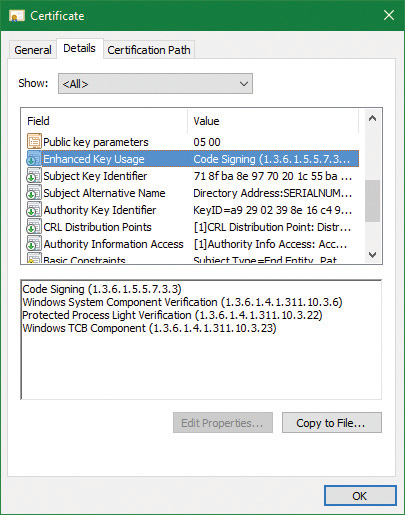
At this point you may be wondering what prohibits a malicious process from claiming it is a protected process and shielding itself from anti-malware (AM) applications. Because the Windows Media DRM Certificate is no longer necessary to run as a protected process, Microsoft extended its Code Integrity module to understand two special enhanced key usage (EKU) OIDs that can be encoded in a digital code signing certificate: 1.3.6.1.4.1.311.10.3.22 and 1.3.6.1.4.1.311.10.3.20. Once one of these EKUs is present, hardcoded Signer and Issuer strings in the certificate, combined with additional possible EKUs, are then associated with the various Protected Signer values. For example, the Microsoft Windows Issuer can grant the PsProtectedSignerWindows protected signer value, but only if the EKU for Windows System Component Verification (1.3.6.1.4.1.311.10.3.6) is also present. As an example, Figure 3-7 shows the certificate for Smss.exe, which is permitted to run as WinTcb-Light.
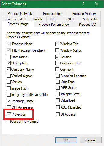
Finally, note that the protection level of a process also impacts which DLLs it will be allowed to load—otherwise, either through a logic bug or simple file replacement or plating, a legitimate protected process could be coerced into loading a third party or malicious library, which would now execute with the same protection level as the process. This check is implemented by granting each process a “Signature Level,” which is stored in the SignatureLevel field of EPROCESS, and then using an internal lookup table to find a corresponding “DLL Signature Level,” stored as SectionSignatureLevel in EPROCESS. Any DLL loading in the process will be checked by the Code Integrity component in the same way that the main executable is verified. For example, a process with “WinTcb” as its executable signer will only load “Windows” or higher signed DLLs.
On Windows 10 and Windows Server 2016, the following processes are PPL signed with WinTcb-Lite: smss.exe, csrss.exe, services.exe, and wininit.exe. Lsass.exe is running as PPL on ARM-based Windows (such as Windows mobile 10) and can run as PPL on x86/x64 if configured as such by a registry setting or by policy (see Chapter 7 for more information). Additionally, certain services are configured to run as Windows PPL or protected processes, such as sppsvc.exe (Software Protection Platform). You may also notice certain service-hosting processes (Svchost.exe) running with this protection level, since many services, such as the AppX Deployment Service and the Windows Subsystem for Linux Service, also run protected. More information on such protected services will be described in Chapter 9 in Part 2.
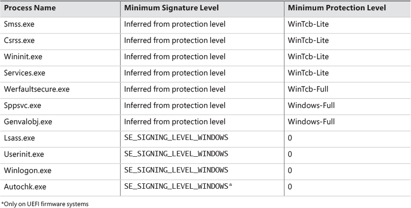
The fact that these core system binaries run as TCB is critical to the security of the system. For example, Csrss.exe has access to certain private APIs implemented by the Window Manager (Win32k.sys), which could give an attacker with Administrator rights access to sensitive parts of the kernel. Similarly, Smss.exe and Wininit.exe implement system startup and management logic that is critical to perform without possible interference from an administrator. Windows guarantees that these binaries will always run as WinTcb-Lite such that, for example, it is not possible for someone to launch them without specifying the correct process protection level in the process attributes when calling CreateProcess. This guarantee is known as the minimum TCB list and forces any processes with the names in Table 3-3 that are in a System path to have a minimum protection level and/or signing level regardless of the caller’s input.
Third-party PPL support
The PPL mechanism extends the protection possibilities for processes beyond executables created solely by Microsoft. A common example is anti-malware (AM) software. A typical AM product consists of three main components:
![]() A kernel driver that intercepts I/O requests to the file system and/or the network, and implements blocking capabilities using object, process, and thread callbacks
A kernel driver that intercepts I/O requests to the file system and/or the network, and implements blocking capabilities using object, process, and thread callbacks
![]() A user-mode service (typically running under a privileged account) that configures the driver’s policies, receives notifications from the driver regarding “interesting” events (for example, infected file), and may communicate with a local server or the Internet
A user-mode service (typically running under a privileged account) that configures the driver’s policies, receives notifications from the driver regarding “interesting” events (for example, infected file), and may communicate with a local server or the Internet
![]() A user-mode GUI process that communicates information to the user and optionally allows the user to make decisions where applicable.
A user-mode GUI process that communicates information to the user and optionally allows the user to make decisions where applicable.
One possible way malware can attack a system is by managing to inject code inside a process running with elevated privileges, or better, inject code specifically inside an anti-malware service and thus tamper with it or disable its operation. If, however, the AM service could run as a PPL, no code injection would be possible, and no process termination would be allowed, meaning that the AM software would be better protected from malware that does not employ kernel-level exploits.
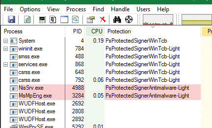
To enable this use, the AM kernel driver described above needs to have a corresponding Early-Launch Anti Malware (ELAM) driver. While ELAM is further described in Chapter 7, the key distinction is that such drivers require a special anti-malware certificate provided by Microsoft (after proper verification of the software’s publisher). Once such a driver is installed, it can contain a custom resource section in its main executable (PE) file called ELAMCERTIFICATEINFO. This section can describe three additional Signers (identified by their public key), each having up to three additional EKUs (identified by OID). Once the Code Integrity system recognizes any file signed by one of the three Signers, containing one of the three EKUs, it permits the process to request a PPL of PS_PROTECTED_ANTIMALWARE_LIGHT (0x31). A canonical example of this is Microsoft’s own AM known as Windows Defender. Its service on Windows 10 (MsMpEng.exe) is signed with the anti-malware certificate for better protection against malware attacking the AM itself, as is its Network Inspection Server (NisSvc.exe).
Minimal and Pico processes
The types of processes we’ve looked at so far, and their data structures, seem to imply that their use is the execution of user-mode code, and that they contain a great deal of related data structures in memory to achieve this. Yet, not all processes are used for this purpose. For example, as we’ve seen, the System process is merely used as a container of most of the system threads, such that their execution time doesn’t pollute arbitrary user-mode processes, as well as being used as a container of drivers’ handles (called kernel handles), such that these don’t end up owned by an arbitrary application either.
Minimal processes
When a specific flag is given to the NtCreateProcessEx function, and the caller is kernel-mode, the function behaves slightly differently and causes the execution of the PsCreateMinimalProcess API. In turn, this causes a process to be created without many of the structures that we saw earlier, namely:
![]() No user-mode address space will be set up, so no PEB and related structures will exist.
No user-mode address space will be set up, so no PEB and related structures will exist.
![]() No NTDLL will be mapped into the process, nor will any loaderhttps://learning.oreilly.com/API Set information.
No NTDLL will be mapped into the process, nor will any loaderhttps://learning.oreilly.com/API Set information.
![]() No section object will be tied to the process, meaning no executable image file is associated to its execution or its name (which can be empty, or an arbitrary string).
No section object will be tied to the process, meaning no executable image file is associated to its execution or its name (which can be empty, or an arbitrary string).
![]() The
The Minimal flag will be set in the EPROCESS flags, causing all threads to become minimal threads, and also avoid any user-mode allocations such as their TEB or user-mode stack. (See Chapter 4 for more information on the TEB.)
As we saw in Chapter 2, Windows 10 has at least two minimal processes—the System process and Memory Compression process—and can have a third, the Secure System process, if Virtualization-Based Security is enabled, which is described further in Chapter 2 and Chapter 7.
Finally, the other way to have minimal processes running on a Windows 10 system is to enable the Windows Subsystem for Linux (WSL) optional feature that was also described in Chapter 2. This will install an inbox Pico Provider composed of the Lxss.sys and LxCore.sys drivers.
Pico processes
While minimal processes have a limited use in terms of allowing access to user-mode virtual address space from kernel components and protecting it, Pico processes take on a more important role by permitting a special component, called a Pico Provider, to control most aspects of their execution from an operating system perspective. This level of control ultimately allows such a provider to emulate the behavior of a completely different operating system kernel, without the underlying user-mode binary being aware that it is running on a Windows-based operating system. This is essentially an implementation of the Drawbridge project from Microsoft Research, which is also used to support SQL Server for Linux in a similar way (albeit with a Windows-based Library OS on top of the Linux kernel).
To support the existence of Pico processes on the system, a provider must first be present. Such a provider can be registered with the PsRegisterPicoProvider API, but subject to a very specific rule: A Pico provider must be loaded before any other third-party drivers are loaded (including boot drivers). In fact, only one of the limited set of a dozen or so core drivers are allowed to call this API before the functionality is disabled, and these core drivers must be signed with a Microsoft Signer Certificate and Windows Component EKU. On Windows systems with the optional WSL component enabled, this core driver is called Lxss.sys, and serves as a stub driver until another driver, LxCore.sys, loads a bit later and takes over the Pico provider responsibilities by transferring the various dispatch tables over to itself. Additionally, note that at the time of this writing, only one such core driver can register itself as a Pico provider.
When a Pico provider calls the registration API, it receives a set of function pointers, which allow it to create and manage Pico processes:
![]() One function to create a Pico process and one to create a Pico thread.
One function to create a Pico process and one to create a Pico thread.
![]() One function to get the context (an arbitrary pointer that the provider can use to store specific data) of a Pico process, one to set it, and another pair of functions to do the same for Pico threads. This will populate the
One function to get the context (an arbitrary pointer that the provider can use to store specific data) of a Pico process, one to set it, and another pair of functions to do the same for Pico threads. This will populate the PicoContext field in ETHREAD and/or EPROCESS.
![]() One function to get the CPU context structure (
One function to get the CPU context structure (CONTEXT) of a Pico thread and one to set it.
![]() A function to change the
A function to change the FS and/or GS segments of a Pico thread, which are normally used by user-mode code to point to some thread local structure (such as the TEB on Windows).
![]() One function to terminate a Pico thread and one to do the same to a Pico process.
One function to terminate a Pico thread and one to do the same to a Pico process.
![]() One function to suspend a Pico thread and one to resume it.
One function to suspend a Pico thread and one to resume it.
As you can see, through these functions, the Pico provider can now create fully custom processes and threads for whom it controls the initial starting state, segment registers, and associate data. However, this alone would not allow the ability to emulate another operating system. A second set of function pointers is transferred, this time from the provider to the kernel, which serve as callbacks whenever certain activities of interest will be performed by a Pico thread or process.
![]() A callback whenever a Pico thread makes a system call using the
A callback whenever a Pico thread makes a system call using the SYSCALL instruction
![]() A callback whenever an exception is raised from a Pico thread
A callback whenever an exception is raised from a Pico thread
![]() A callback whenever a fault during a probe and lock operation on a memory descriptor list (MDL) occurs inside a Pico thread
A callback whenever a fault during a probe and lock operation on a memory descriptor list (MDL) occurs inside a Pico thread
![]() A callback whenever a caller is requesting the name of a Pico process
A callback whenever a caller is requesting the name of a Pico process
![]() A callback whenever Event Tracing for Windows (ETW) is requesting the user-mode stack trace of a Pico process
A callback whenever Event Tracing for Windows (ETW) is requesting the user-mode stack trace of a Pico process
![]() A callback whenever an application attempts to open a handle to a Pico process or Pico thread
A callback whenever an application attempts to open a handle to a Pico process or Pico thread
![]() A callback whenever someone requests the termination of a Pico process
A callback whenever someone requests the termination of a Pico process
![]() A callback whenever a Pico thread or Pico process terminates unexpectedly
A callback whenever a Pico thread or Pico process terminates unexpectedly
Additionally, a Pico provider also leverages Kernel Patch Protection (KPP), described in Chapter 7, to both protect its callbacks and system calls as well as prevent fraudulent or malicious Pico providers from registering on top of a legitimate Pico provider.
It now becomes clear that with such unparalleled access to any possible user-kernel transition or visible kernel-user interactions between a Pico process/thread and the world, it can be fully encapsulated by a Pico provider (and relevant user-mode libraries) to wrap a completely different kernel implementation than that of Windows (with some exceptions, of course, as thread scheduling rules and memory management rules, such as commit, still apply). Correctly written applications are not supposed to be sensitive to such internal algorithms, as they are subject to change even within the operating system they normally execute on.
Therefore, Pico providers are essentially custom-written kernel modules that implement the necessary callbacks to respond to the list of possible events (shown earlier) that a Pico process can cause to arise. This is how WSL is capable of running unmodified Linux ELF binaries in user-mode, limited only by the completeness of its system call emulation and related functionality.
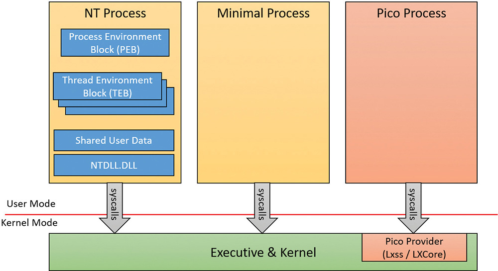
To complete the picture on regular NT processes versus minimal processes versus Pico processes, we present Figure 3-8, showing the different structures for each.
Trustlets (secure processes)
As covered in Chapter 2, Windows contains new virtualization-based security (VBS) features such as Device Guard and Credential Guard, which enhance the safety of the operating system and user data by leveraging the hypervisor. We saw how one such feature, Credential Guard (which is discussed at length in Chapter 7), runs in a new Isolated User Mode environment, which, while still unprivileged (ring 3), has a virtual trust level of 1 (VTL 1), granting it protection from the regular VTL 0 world in which both the NT kernel (ring 0) and applications (ring 3) live. Let’s investigate how the kernel sets up such processes for execution, and the various data structures such processes use.
Trustlet structure
To begin with, although Trustlets are regular Windows Portable Executables (PE) files, they contain some IUM-specific properties:
![]() They can import only from a limited set of Windows system DLLs (C/C++ Runtime, KernelBase, Advapi, RPC Runtime, CNG Base Crypto, and NTDLL) due to the restricted number of system calls that are available to Trustlets. Note that mathematical DLLs that operate only on data structures (such as NTLM, ASN.1, etc.) are also usable, as they don’t perform any system calls.
They can import only from a limited set of Windows system DLLs (C/C++ Runtime, KernelBase, Advapi, RPC Runtime, CNG Base Crypto, and NTDLL) due to the restricted number of system calls that are available to Trustlets. Note that mathematical DLLs that operate only on data structures (such as NTLM, ASN.1, etc.) are also usable, as they don’t perform any system calls.
![]() They can import from an IUM-specific system DLL that is made available to them, called
They can import from an IUM-specific system DLL that is made available to them, called Iumbase, which provides the Base IUM System API, containing support for mailslots, storage boxes, cryptography, and more. This library ends up calling into Iumdll.dll, which is the VTL 1 version of Ntdll.dll, and contains secure system calls (system calls that are implemented by the Secure Kernel, and not passed on to the Normal VTL 0 Kernel).
![]() They contain a PE section named
They contain a PE section named .tPolicy with an exported global variable named s_IumPolicyMetadata. This serves as metadata for the Secure Kernel to implement policy settings around permitting VTL 0 access to the Trustlet (such as allowing debugging, crash dump support, etc.).
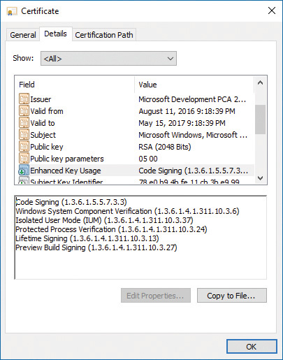
![]() They are signed with a certificate that contains the Isolated User Mode EKU (1.3.6.1.4.1.311.10.3.37). Figure 3-9 shows the certificate data for LsaIso.exe, showing its IUM EKU.
They are signed with a certificate that contains the Isolated User Mode EKU (1.3.6.1.4.1.311.10.3.37). Figure 3-9 shows the certificate data for LsaIso.exe, showing its IUM EKU.
Additionally, Trustlets must be launched by using a specific process attribute when using CreateProcess—both to request their execution in IUM as well as to specify launch properties. We will describe both the policy metadata and the process attributes in the following sections.
Trustlet policy metadata
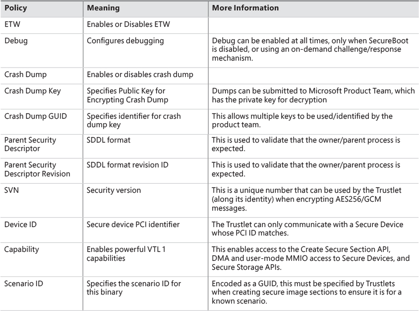
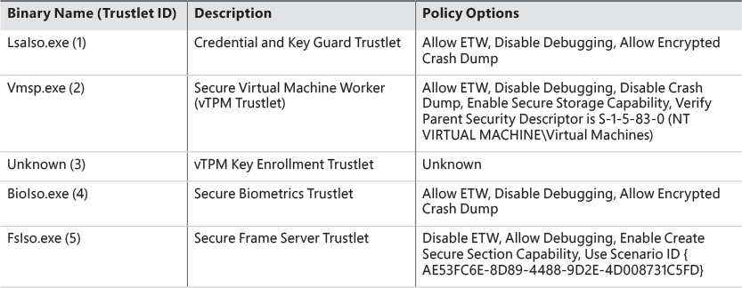
The policy metadata includes various options for configuring how “accessible” the Trustlet will be from VTL 0. It is described by a structure present at the s_IumPolicyMetadata export mentioned earlier, and contains a version number (currently set to 1) as well as the Trustlet ID, which is a unique number that identifies this specific Trustlet among the ones that are known to exist (for example, BioIso.exe is Trustlet ID 4). Finally, the metadata has an array of policy options. Currently, the options listed in Table 3-4 are supported. It should be obvious that as these policies are part of the signed executable data, attempting to modify them would invalidate the IUM signature and prohibit execution.
Trustlet attributes
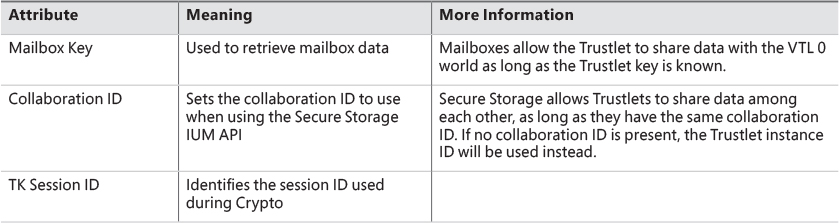
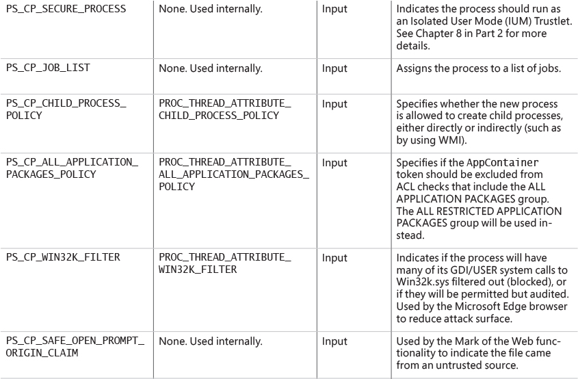
Launching a Trustlet requires correct usage of the PS_CP_SECURE_PROCESS attribute, which is first used to authenticate that the caller truly wants to create a Trustlet, as well as to verify that the Trustlet the caller thinks its executing is actually the Trustlet being executed. This is done by embedding a Trustlet identifier in the attribute, which must match the Trustlet ID contained in the policy metadata. Then, one or more attributes can be specified, which are shown in Table 3-5.
System built-in Trustlets
At the time of this writing, Windows 10 contains five different Trustlets, which are identified by their identity numbers. They are described in Table 3-6. Note that Trustlet ID 0 represents the Secure Kernel itself.
Trustlet identity
Trustlets have multiple forms of identity that they can use on the system:
![]() Trustlet identifier or Trustlet ID This is a hard-coded integer in the Trustlet’s policy metadata, which also must be used in the Trustlet process-creation attributes. It ensures that the system knows there are only a handful of Trustlets, and that the callers are launching the expected one.
Trustlet identifier or Trustlet ID This is a hard-coded integer in the Trustlet’s policy metadata, which also must be used in the Trustlet process-creation attributes. It ensures that the system knows there are only a handful of Trustlets, and that the callers are launching the expected one.
![]() Trustlet instance This is a cryptographically secure 16-byte random number generated by the Secure Kernel. Without the use of a collaboration ID, the Trustlet instance is what’s used to guarantee that Secure Storage APIs will only allow this one instance of the Trustlet to get/put data into its storage blob.
Trustlet instance This is a cryptographically secure 16-byte random number generated by the Secure Kernel. Without the use of a collaboration ID, the Trustlet instance is what’s used to guarantee that Secure Storage APIs will only allow this one instance of the Trustlet to get/put data into its storage blob.
![]() Collaboration ID This is used when a Trustlet would like to allow other Trustlets with the same ID, or other instances of the same Trustlet, to share access to the same Secure Storage blob. When this ID is present, the instance ID of the Trustlet will be ignored when calling the Get or Put APIs.
Collaboration ID This is used when a Trustlet would like to allow other Trustlets with the same ID, or other instances of the same Trustlet, to share access to the same Secure Storage blob. When this ID is present, the instance ID of the Trustlet will be ignored when calling the Get or Put APIs.
![]() Security version (SVN) This is used for Trustlets that require strong cryptographic proof of provenance of signed or encrypted data. It is used when encrypting AES256/GCM data by Credential and Key Guard, and is also used by the Cryptograph Report service.
Security version (SVN) This is used for Trustlets that require strong cryptographic proof of provenance of signed or encrypted data. It is used when encrypting AES256/GCM data by Credential and Key Guard, and is also used by the Cryptograph Report service.
![]() Scenario ID This is used for Trustlets that create named (identity-based) secure kernel objects, such as secure sections. This GUID validates that the Trustlet is creating such objects as part of a predetermined scenario, by tagging them in the namespace with this GUID. As such, other Trustlets wishing to open the same named objects would thus have to have the same scenario ID. Note that more than one scenario ID can actually be present, but no Trustlets currently use more than one.
Scenario ID This is used for Trustlets that create named (identity-based) secure kernel objects, such as secure sections. This GUID validates that the Trustlet is creating such objects as part of a predetermined scenario, by tagging them in the namespace with this GUID. As such, other Trustlets wishing to open the same named objects would thus have to have the same scenario ID. Note that more than one scenario ID can actually be present, but no Trustlets currently use more than one.
Isolated user-mode services
The benefits of running as a Trustlet not only include protection from attacks from the normal (VTL 0) world, but also access to privileged and protected secure system calls that are only offered by the Secure Kernel to Trustlets. These include the following services:
![]() Secure Devices (
Secure Devices (IumCreateSecureDevice, IumDmaMapMemory, IumGetDmaEnabler, IumMap-SecureIo, IumProtectSecureIo, IumQuerySecureDeviceInformation, IopUnmapSecureIo, IumUpdateSecureDeviceState) These provide access to secure ACPI and/or PCI devices, which cannot be accessed from VTL 0 and are exclusively owned by the Secure Kernel (and its ancillary Secure HAL and Secure PCI services). Trustlets with the relevant capabilities (see the “Trustlet policy metadata” section earlier in this chapter) can map the registers of such a device in VTL 1 IUM, as well as potentially perform Direct Memory Access (DMA) transfers. Additionally, Trustlets can serve as user-mode device drivers for such hardware by using the Secure Device Framework (SDF) located in SDFHost.dll. This functionality is leveraged for Secure Biometrics for Windows Hello, such as Secure USB Smartcard (over PCI) or Webcam/Fingerprint Sensors (over ACPI).
![]() Secure Sections (
Secure Sections (IumCreateSecureSection, IumFlushSecureSectionBuffers, IumGetExposed- SecureSection, IumOpenSecureSection) These provide the ability to both share physical pages with a VTL 0 driver (which would use VslCreateSecureSection) through exposed secure sections, as well as share data solely within VTL 1 as named secured sections (leveraging the identity-based mechanism described earlier in the “Trustlet identity” section) with other Trustlets or other instances of the same Trustlet. Trustlets require the Secure Section capability described in the “Trustlet policy metadata” section to use these features.
![]() Mailboxes (
Mailboxes (IumPostMailbox) This enables a Trustlet to share up to eight slots of about up to 4 KB of data with a component in the normal (VTL 0) kernel, which can call VslRetrieveMailbox passing in the slot identifier and secret mailbox key. For example, Vid.sys in VTL 0 uses this to retrieve various secrets used by the vTPM feature from the Vmsp.exe Trustlet.
![]() Identity Keys (
Identity Keys (IumGetIdk) This allows a Trustlet to obtain either a unique identifying decryption key or signing key. This key material is unique to the machine and can be obtained only from a Trustlet. It is an essential part of the Credential Guard feature to uniquely authenticate the machine and that credentials are coming from IUM.
![]() Cryptographic Services (
Cryptographic Services (IumCrypto) This allows a Trustlet to encrypt and decrypt data with a local and/or per-boot session key generated by the Secure Kernel that is only available to IUM, to obtain a TPM binding handle, to get the FIPS mode of the Secure Kernel, and to obtain a random number generator (RNG) seed only generated by the Secure Kernel for IUM. It also enables a Trustlet to generate an IDK-signed, SHA-2 hashed, and timestamped report with the identity and SVN of the Trustlet, a dump of its policy metadata, whether or not it was ever attached to a debugger, and any other Trustlet-controlled data requested. This can be used as a sort of TPM-like measurement of the Trustlet to prove that it was not tampered with.
![]() Secure Storage (
Secure Storage (IumSecureStorageGet, IumSecureStoragePut) This allows Trustlets that have the Secure Storage capability (described earlier in the “Trustlet policy metadata” section) to store arbitrarily sized storage blobs and to later retrieve them, either based on their unique Trustlet instance or by sharing the same collaboration ID as another Trustlet.
Trustlet-accessible system calls
As the Secure Kernel attempts to minimize its attack surface and exposure, it only provides a subset (less than 50) of all of the hundreds of system calls that a normal (VTL 0) application can use. These system calls are the strict minimum necessary for compatibility with the system DLLs that Trustlets can use (refer to the section “Trustlet structure” to see these), as well as the specific services required to support the RPC runtime (Rpcrt4.dll) and ETW tracing.
![]() Worker Factory and Thread APIs These support the Thread Pool API (used by RPC) and TLS Slots used by the Loader.
Worker Factory and Thread APIs These support the Thread Pool API (used by RPC) and TLS Slots used by the Loader.
![]() Process Information API This supports TLS Slots and Thread Stack Allocation.
Process Information API This supports TLS Slots and Thread Stack Allocation.
![]() Event, Semaphore, Wait, and Completion APIs These support Thread Pool and Synchronization.
Event, Semaphore, Wait, and Completion APIs These support Thread Pool and Synchronization.
![]() Advanced Local Procedure Call (ALPC) APIs These support Local RPC over the ncalrpc transport.
Advanced Local Procedure Call (ALPC) APIs These support Local RPC over the ncalrpc transport.
![]() System Information API This supports reading Secure Boot information, basic and NUMA system information for Kernel32.dll and Thread Pool scaling, performance, and subsets of time information.
System Information API This supports reading Secure Boot information, basic and NUMA system information for Kernel32.dll and Thread Pool scaling, performance, and subsets of time information.
![]() Token API This provides minimal support for RPC impersonation.
Token API This provides minimal support for RPC impersonation.
![]() Virtual Memory Allocation APIs These support allocations by the User-Mode Heap Manager.
Virtual Memory Allocation APIs These support allocations by the User-Mode Heap Manager.
![]() Section APIs These support the Loader (for DLL Images) as well as the Secure Section functionality (once created/exposed through secure system calls shown earlier).
Section APIs These support the Loader (for DLL Images) as well as the Secure Section functionality (once created/exposed through secure system calls shown earlier).
![]() Trace Control API This supports ETW.
Trace Control API This supports ETW.
![]() Exception and Continue API This supports Structured Exception Handling (SEH).
Exception and Continue API This supports Structured Exception Handling (SEH).
It should be evident from this list that support for operations such as Device I/O, whether on files or actual physical devices, is not possible (there is no CreateFile API, to begin with), as is also the case for Registry I/O. Nor is the creation of other processes, or any sort of graphics API usage (there is no Win32k.sys driver in VTL 1). As such, Trustlets are meant to be isolated workhorse back-ends (in VTL 1) of their complex front-ends (in VTL 0), having only ALPC as a communication mechanism, or exposed secure sections (whose handle would have to had been communicated to them through ALPC). In Chapter 7 (Security), we’ll look in more detail into the implementation of a specific Trustlet—LsaIso.exe, which provides Credential and Key Guard.
Flow of CreateProcess
We’ve shown the various data structures involved in process-state manipulation and management and how various tools and debugger commands can inspect this information. In this section, we’ll see how and when those data structures are created and filled out, as well as the overall creation and termination behaviors behind processes. As we’ve seen, all documented process-creation functions eventually end up calling CreateProcessInternalW, so this is where we start.
Creating a Windows process consists of several stages carried out in three parts of the operating system: the Windows client-side library Kernel32.dll (the real work starting with CreateProcessInternalW), the Windows executive, and the Windows subsystem process (Csrss). Because of the multiple-environment subsystem architecture of Windows, creating an executive process object (which other subsystems can use) is separated from the work involved in creating a Windows subsystem process. So, although the following description of the flow of the Windows CreateProcess function is complicated, keep in mind that part of the work is specific to the semantics added by the Windows subsystem as opposed to the core work needed to create an executive process object.
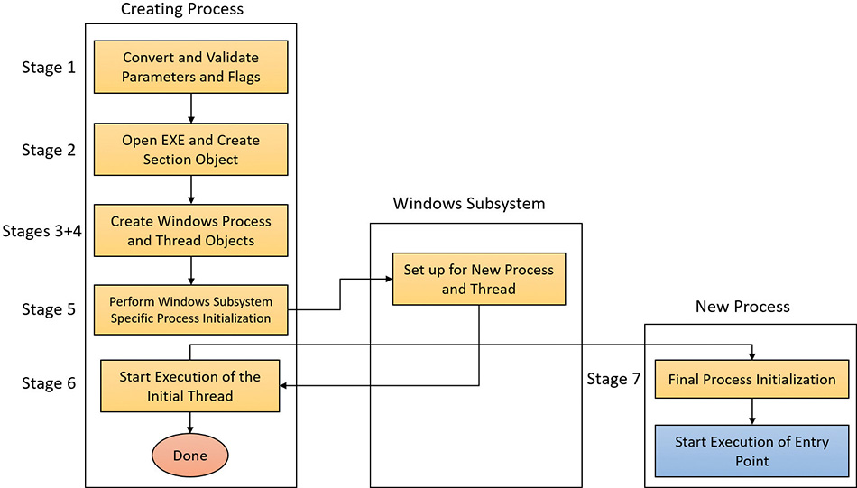
The following list summarizes the main stages of creating a process with the Windows CreateProcess* functions. The operations performed in each stage are described in detail in the subsequent sections.
![]() Note
Note
Many steps of CreateProcess are related to the setup of the process virtual address space and therefore refer to many memory-management terms and structures that are defined in Chapter 5.
1. Validate parameters; convert Windows subsystem flags and options to their native counterparts; parse, validate, and convert the attribute list to its native counterpart.
2. Open the image file (.exe) to be executed inside the process.
3. Create the Windows executive process object.
4. Create the initial thread (stack, context, and Windows executive thread object).
5. Perform post-creation, Windows subsystem–specific process initialization.
6. Start execution of the initial thread (unless the CREATE_SUSPENDED flag was specified).
7. In the context of the new process and thread, complete the initialization of the address space (for example, load required DLLs) and begin execution of the program’s entry point.
Figure 3-10 shows an overview of the stages Windows follows to create a process.
Stage 1: Converting and validating parameters and flags
Before opening the executable image to run, CreateProcessInternalW performs the following steps:
1. The priority class for the new process is specified as independent bits in the CreationFlags parameter to the CreateProcess* functions. Thus, you can specify more than one priority class for a single CreateProcess* call. Windows resolves the question of which priority class to assign to the process by choosing the lowest-priority class set.
There are six process priority classes defined, each value mapped to a number:
• Idle or Low, as Task Manager displays it (4)
• Below Normal (6)
• Normal (8)
• Above Normal (10)
• High (13)
• Real-time (24)
The priority class is used as the base priority for threads created in that process. This value does not directly affect the process itself—only the threads inside it. A description of process priority class and its effects on thread scheduling appears in Chapter 4.
2. If no priority class is specified for the new process, the priority class defaults to Normal. If a Real-time priority class is specified for the new process and the process’s caller doesn’t have the Increase Scheduling Priority privilege (SE_INC_BASE_PRIORITY_NAME), the High priority class is used instead. In other words, process creation doesn’t fail just because the caller has insufficient privileges to create the process in the Real-time priority class; the new process just won’t have as high a priority as Real-time.
3. If the creation flags specify that the process will be debugged, Kernel32 initiates a connection to the native debugging code in Ntdll.dll by calling DbgUiConnectToDbg and gets a handle to the debug object from the current thread’s environment block (TEB).
4. Kernel32.dll sets the default hard error mode if the creation flags specified one.
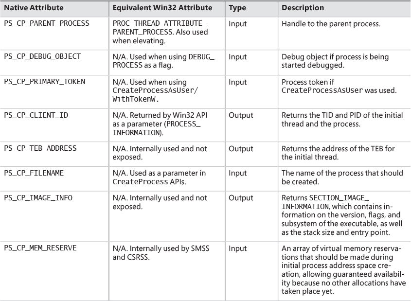
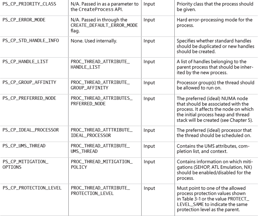
5. The user-specified attribute list is converted from Windows subsystem format to native format and internal attributes are added to it. The possible attributes that can be added to the attribute list are listed in Table 3-7, including their documented Windows API counterparts, if any.
![]() Note
Note
The attribute list passed on CreateProcess* calls permits passing back to the caller information beyond a simple status code, such as the TEB address of the initial thread or information on the image section. This is necessary for protected processes because the parent cannot query this information after the child is created.
6. If the process is part of a job object, but the creation flags requested a separate virtual DOS machine (VDM), the flag is ignored.
7. The security attributes for the process and initial thread that were supplied to the CreateProcess function are converted to their internal representation (OBJECT_ATTRIBUTES structures, documented in the WDK).
8. CreateProcessInternalW checks whether the process should be created as modern. The process is to be created modern if specified so by an attribute (PROC_THREAD_ATTRIBUTE_ PACKAGE_FULL_NAME) with the full package name or the creator is itself modern (and a parent process has not been explicitly specified by the PROC_THREAD_ATTRIBUTE_PARENT_PROCESS attribute). If so, a call is made to the internal BasepAppXExtension to gather more contextual information on the modern app parameters described by a structure called APPX_PROCESS_CONTEXT. This structure holds information such as the package name (internally referred to as package moniker), the capabilities associated with the app, the current directory for the process, and whether the app should have full trust. The option of creating full trust modern apps is not publicly exposed, and is reserved for apps that have the modern look and feel but perform system- level operations. A canonical example is the Settings app in Windows 10 (SystemSettings.exe).
9. If the process is to be created as modern, the security capabilities (if provided by PROC_THREAD_ATTRIBUTE_SECURITY_CAPABILITIES) are recorded for the initial token creation by calling the internal BasepCreateLowBox function. The term LowBox refers to the sandbox (AppContainer) under which the process is to be executed. Note that although creating modern processes by directly calling CreateProcess is not supported (instead, the COM interfaces described earlier should be used), the Windows SDK and MSDN do document the ability to create AppContainer legacy desktop applications by passing this attribute.
10. If a modern process is to be created, then a flag is set to indicate to the kernel to skip embedded manifest detection. Modern processes should never have an embedded manifest as it’s simply not needed. (A modern app has a manifest of its own, unrelated to the embedded manifest referenced here.)
11. If the debug flag has been specified (DEBUG_PROCESS), then the Debugger value under the Image File Execution Options registry key (discussed in the next section) for the executable is marked to be skipped. Otherwise, a debugger will never be able to create its debuggee process because the creation will enter an infinite loop (trying to create the debugger process over and over again).
12. All windows are associated with desktops, the graphical representation of a workspace. If no desktop is specified in the STARTUPINFO structure, the process is associated with the caller’s current desktop.
![]() Note
Note
The Windows 10 Virtual Desktop feature does not use multiple desktop objects (in the kernel object sense). There is still one desktop, but windows are shown and hidden as required. This is in contrast to the Sysinternals desktops.exe tool, which really creates up to four desktop objects. The difference can be felt when trying to move a window from one desktop to another. In the case of desktops.exe, it can’t be done, as such an operation is not supported in Windows. On the other hand, Windows 10’s Virtual Desktop allows it, since there is no real “moving” going on.
13. The application and command-line arguments passed to CreateProcessInternalW are analyzed. The executable path name is converted to the internal NT name (for example, c:\temp\a.exe turns into something like \device\harddiskvolume1\temp\a.exe) because some functions require it in that format.
14. Most of the gathered information is converted to a single large structure of type RTL_USER_PROCESS_PARAMETERS.
Once these steps are completed, CreateProcessInternalW performs the initial call to NtCreate-UserProcess to attempt creation of the process. Because Kernel32.dll has no idea at this point whether the application image name is a real Windows application or a batch file (.bat or .cmd), 16-bit, or DOS application, the call might fail, at which point CreateProcessInternalW looks at the error reason and attempts to correct the situation.
Stage 2: Opening the image to be executed
At this point, the creating thread has switched into kernel mode and continues the work within the NtCreateUserProcess system call implementation.
1. NtCreateUserProcess first validates arguments and builds an internal structure to hold all creation information. The reason for validating arguments again is to make sure the call to the executive did not originate from a hack that managed to simulate the way Ntdll.dll makes the transition to the kernel with bogus or malicious arguments.
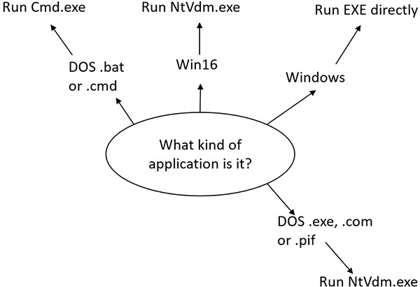
2. As illustrated in Figure 3-11, the next stage in NtCreateUserProcess is to find the appropriate Windows image that will run the executable file specified by the caller and to create a section object to later map it into the address space of the new process. If the call fails for any reason, it returns to CreateProcessInternalW with a failure state (look ahead to Table 3-8) that causes CreateProcessInternalW to attempt execution again.
3. If the process needs to be created protected, it also checks the signing policy.
4. If the process to be created is modern, a licensing check is done to make sure it’s licensed and allowed to run. If the app is inbox (preinstalled with Windows), it’s allowed to run regardless of license. If sideloading apps is allowed (configured through the Settings app), then any signed app can be executed, not just from the store.
5. If the process is a Trustlet, the section object must be created with a special flag that allows the secure kernel to use it.
6. If the executable file specified is a Windows EXE, NtCreateUserProcess tries to open the file and create a section object for it. The object isn’t mapped into memory yet, but it is opened. Just because a section object has been successfully created doesn’t mean the file is a valid Windows image, however. It could be a DLL or a POSIX executable. If the file is a POSIX executable, the call fails, because POSIX is no longer supported. If the file is a DLL, CreateProcessInternalW fails as well.
7. Now that NtCreateUserProcess has found a valid Windows executable image, as part of the process creation code described in the next section, it looks in the registry under HKLM\ SOFTWARE\Microsoft\Windows NT\CurrentVersion\Image File Execution Options to see whether a subkey with the file name and extension of the executable image (but without the directory and path information—for example, Notepad.exe) exists there. If it does, PspAllocate-Process looks for a value named Debugger for that key. If this value is present, the image to be run becomes the string in that value and CreateProcessInternalW restarts at stage 1.
![]() Tip
Tip
You can take advantage of this process-creation behavior and debug the startup code of Windows services processes before they start rather than attach the debugger after starting a service, which doesn’t allow you to debug the startup code.
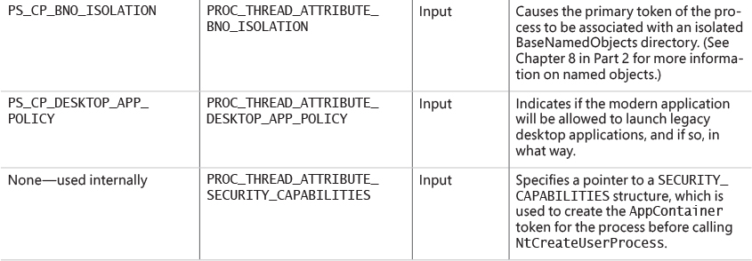
8. On the other hand, if the image is not a Windows EXE (for example, if it’s an MS-DOS or a Win16 application), CreateProcessInternalW goes through a series of steps to find a Windows support image to run it. This process is necessary because non-Windows applications aren’t run directly. Windows instead uses one of a few special support images that, in turn, are responsible for actually running the non-Windows program. For example, if you attempt to run an MS-DOS or a Win16 executable (32-bit Windows only), the image to be run becomes the Windows executable Ntvdm.exe. In short, you can’t directly create a process that is not a Windows process. If Windows can’t find a way to resolve the activated image as a Windows process (as shown in Table 3-8), CreateProcessInternalW fails.
Specifically, the decision tree that CreateProcessInternalW goes through to run an image is as follows:
• If it’s x86 32-bit Windows, and the image is an MS-DOS application with an .exe, .com, or .pif extension, a message is sent to the Windows subsystem to check whether an MS-DOS support process (Ntvdm.exe, specified in the HKLM\SYSTEM\CurrentControlSet\Control\WOW\cmdline registry value) has already been created for this session. If a support process has been created, it is used to run the MS-DOS application. (The Windows subsystem sends the message to the virtual DOS machine [VDM] process to run the new image.) Then Create-ProcessInternalW returns. If a support process hasn’t been created, the image to be run changes to Ntvdm.exe and CreateProcessInternalW restarts at stage 1.
• If the file to run has a .bat or .cmd extension, the image to be run becomes Cmd.exe, the Windows command prompt, and CreateProcessInternalW restarts at stage 1. (The name of the batch file is passed as the second parameter to Cmd.exe after the /c switch.)
• For an x86 Windows system, if the image is a Win16 (Windows 3.1) executable, CreateProcess-InternalW must decide whether a new VDM process must be created to run it or whether it should use the default session-wide shared VDM process (which might not yet have been created). The CreateProcess flags CREATE_SEPARATE_WOW_VDM and CREATE_SHARED_WOW_VDM control this decision. If these flags aren’t specified, the HKLM\SYSTEM\CurrentControlSet\ Control\WOW\DefaultSeparateVDM registry value dictates the default behavior. If the application is to be run in a separate VDM, the image to be run changes to Ntvdm.exe followed by some configuration parameters and the 16-bit process name, and CreateProcess-InternalW restarts at stage 1. Otherwise, the Windows subsystem sends a message to see whether the shared VDM process exists and can be used. (If the VDM process is running on a different desktop or isn’t running under the same security as the caller, it can’t be used, and a new VDM process must be created.) If a shared VDM process can be used, the Windows subsystem sends a message to it to run the new image and CreateProcessInternalW returns. If the VDM process hasn’t yet been created (or if it exists but can’t be used), the image to be run changes to the VDM support image and CreateProcessInternalW restarts at stage 1.
Stage 3: Creating the Windows executive process object
At this point, NtCreateUserProcess has opened a valid Windows executable file and created a section object to map it into the new process address space. Next, it creates a Windows executive process object to run the image by calling the internal system function PspAllocateProcess. Creating the executive process object (which is done by the creating thread) involves the following sub-stages:
3A. Setting up the EPROCESS object
3B. Creating the initial process address space
3C. Initializing the kernel process structure (KPROCESS)
3D. Concluding the setup of the process address space
3E. Setting up the PEB
3F. Completing the setup of the executive process object
![]() Note
Note
The only time there won’t be a parent process is during system initialization (when the System process is created). After that point, a parent process is always required to provide a security context for the new process.
Stage 3A: Setting up the EPROCESS object
This sub-stage involves the following steps:
1. Inherit the affinity of the parent process unless it was explicitly set during process creation (through the attribute list).
2. Choose the ideal NUMA node that was specified in the attribute list, if any.
3. Inherit the I/O and page priority from the parent process. If there is no parent process, the default page priority (5) and I/O priority (Normal) are used.
4. Set the new process exit status to STATUS_PENDING.
5. Choose the hard error processing mode selected by the attribute list. Otherwise, inherit the parent’s processing mode if none was given. If no parent exists, use the default processing mode, which is to display all errors.
6. Store the parent process’s ID in the InheritedFromUniqueProcessId field in the new process object.
7. Query the Image File Execution Options (IFEO) key to check if the process should be mapped with large pages (UseLargePages value in the IFEO key), unless the process is to run under Wow64, in which case large pages will not be used. Also, query the key to check if NTDLL has been listed as a DLL that should be mapped with large pages within this process.
8. Query the performance options key in IFEO (PerfOptions, if it exists), which may consist of any number of the following possible values: IoPriority, PagePriority, CpuPriorityClass, and WorkingSetLimitInKB.
9. If the process would run under Wow64, then allocate the Wow64 auxiliary structure (EWOW64PROCESS) and set it in the WoW64Process member of the EPROCESS structure.
10. If the process is to be created inside an AppContainer (in most cases a modern app), validate that the token was created with a LowBox. (See Chapter 7 for more on AppContainers.)
11. Attempt to acquire all the privileges required for creating the process. Choosing the Real-time process priority class, assigning a token to the new process, mapping the process with large pages, and creating the process within a new session are all operations that require the appropriate privilege.
12. Create the process’s primary access token (a duplicate of its parent’s primary token). New processes inherit the security profile of their parents. If the CreateProcessAsUser function is being used to specify a different access token for the new process, the token is then changed appropriately. This change might happen only if the parent token’s integrity level dominates the integrity level of the access token, and if the access token is a true child or sibling of the parent token. Note that if the parent has the SeAssignPrimaryToken privilege, this will bypass these checks.
13. The session ID of the new process token is now checked to determine if this is a cross-session create. If so, the parent process temporarily attaches to the target session to correctly process quotas and address space creation.
14. Set the new process’s quota block to the address of its parent process’s quota block, and increment the reference count for the parent’s quota block. If the process was created through CreateProcessAsUser, this step won’t occur. Instead, the default quota is created, or a quota matching the user’s profile is selected.
15. The process minimum and maximum working set sizes are set to the values of PspMinimumWorkingSet and PspMaximumWorkingSet, respectively. These values can be overridden if performance options were specified in the PerfOptions key part of Image File Execution Options, in which case the maximum working set is taken from there. Note that the default working set limits are soft limits and are essentially hints, while the PerfOptions working set maximum is a hard limit. (That is, the working set will not be allowed to grow past that number.)
16. Initialize the address space of the process. (See stage 3B.) Then detach from the target session if it was different.
17. The group affinity for the process is now chosen if group-affinity inheritance was not used. The default group affinity will either inherit from the parent if NUMA node propagation was set earlier (the group owning the NUMA node will be used) or be assigned round-robin. If the system is in forced group-awareness mode and group 0 was chosen by the selection algorithm, group 1 is chosen instead, as long as it exists.
18. Initialize the KPROCESS part of the process object. (See Stage 3C.)
19. The token for the process is now set.
20. The process’s priority class is set to normal unless the parent was using idle or the Below Normal process priority class, in which case the parent’s priority is inherited.
21. The process handle table is initialized. If the inherit handles flag is set for the parent process, any inheritable handles are copied from the parent’s object handle table into the new process. (For more information about object handle tables, see Chapter 8 in Part 2.) A process attribute can also be used to specify only a subset of handles, which is useful when you are using CreateProcessAsUser to restrict which objects should be inherited by the child process.
22. If performance options were specified through the PerfOptions key, these are now applied. The PerfOptions key includes overrides for the working set limit, I/O priority, page priority, and CPU priority class of the process.
23. The final process priority class and the default quantum for its threads are computed and set.
24. The various mitigation options provided in the IFEO key (as a single 64-bit value named Mitigation) are read and set. If the process is under an AppContainer, add the TreatAs-AppContainer mitigation flag.
25. All other mitigation flags are now applied.
Stage 3B: Creating the initial process address space
The initial process address space consists of the following pages:
![]() Page directory (it’s possible there’ll be more than one for systems with page tables more than two levels, such as x86 systems in PAE mode or 64-bit systems)
Page directory (it’s possible there’ll be more than one for systems with page tables more than two levels, such as x86 systems in PAE mode or 64-bit systems)
![]() Hyperspace page
Hyperspace page
![]() VAD bitmap page
VAD bitmap page
![]() Working set list
Working set list
To create these pages, the following steps are taken:
1. Page table entries are created in the appropriate page tables to map the initial pages.
2. The number of pages is deducted from the kernel variable MmTotalCommittedPages and added to MmProcessCommit.
3. The system-wide default process minimum working set size (PsMinimumWorkingSet) is deducted from MmResidentAvailablePages.
4. The page table pages for the global system space (that is, other than the process-specific pages we just described, and except session-specific memory) are created.
Stage 3C: Creating the kernel process structure
The next stage of PspAllocateProcess is the initialization of the KPROCESS structure (the Pcb member of the EPROCESS). This work is performed by KeInitializeProcess, which does the following:
1. The doubly linked list, which connects all threads part of the process (initially empty), is initialized.
2. The initial value (or reset value) of the process default quantum (which is described in more detail in the “Thread scheduling” section in Chapter 4) is hard-coded to 6 until it is initialized later (by PspComputeQuantumAndPriority).
![]() Note
Note
The default initial quantum differs between Windows client and server systems. For more information on thread quantums, turn to the discussion in the section “Thread scheduling” in Chapter 4.
3. The process’s base priority is set based on what was computed in stage 3A.
4. The default processor affinity for the threads in the process is set, as is the group affinity. The group affinity was calculated in stage 3A or inherited from the parent.
5. The process-swapping state is set to resident.
6. The thread seed is based on the ideal processor that the kernel has chosen for this process (which is based on the previously created process’s ideal processor, effectively randomizing this in a round-robin manner). Creating a new process will update the seed in KeNodeBlock (the initial NUMA node block) so that the next new process will get a different ideal processor seed.
7. If the process is a secure process (Windows 10 and Server 2016), then its secure ID is created now by calling HvlCreateSecureProcess.
Stage 3D: Concluding the setup of the process address space
Setting up the address space for a new process is somewhat complicated, so let’s look at what’s involved one step at a time. To get the most out of this section, you should have some familiarity with the internals of the Windows memory manager, described in Chapter 5.
The routine that does most of the work in setting the address space is MmInitializeProcess-AddressSpace. It also supports cloning an address space from another process. This capability was useful at the time to implement the POSIX fork system call. It may also be leveraged in the future to support other Unix-style fork (this is how fork is implemented in Windows Subsystem for Linux in Redstone 1). The following steps do not describe the address space cloning functionality, but rather focus on normal process address space initialization.
1. The virtual memory manager sets the value of the process’s last trim time to the current time. The working set manager (which runs in the context of the balance set manager system thread) uses this value to determine when to initiate working set trimming.
2. The memory manager initializes the process’s working set list. Page faults can now be taken.
3. The section (created when the image file was opened) is now mapped into the new process’s address space, and the process section base address is set to the base address of the image.
4. The Process Environment Block (PEB) is created and initialized (see the section stage 3E).
5. Ntdll.dll is mapped into the process. If this is a Wow64 process, the 32-bit Ntdll.dll is also mapped.
6. A new session, if requested, is now created for the process. This special step is mostly implemented for the benefit of the Session Manager (Smss) when initializing a new session.
7. The standard handles are duplicated and the new values are written in the process parameters structure.
8. Any memory reservations listed in the attribute list are now processed. Additionally, two flags allow the bulk reservation of the first 1 or 16 MB of the address space. These flags are used internally for mapping, for example, real-mode vectors and ROM code (which must be in the low ranges of virtual address space, where normally the heap or other process structures could be located).
9. The user process parameters are written into the process, copied, and fixed up (that is, they are converted from absolute form to a relative form so that a single memory block is needed).
10. The affinity information is written into the PEB.
11. The MinWin API redirection set is mapped into the process and its pointer is stored in the PEB.
12. The process unique ID is now determined and stored. The kernel does not distinguish between unique process and thread IDs and handles. The process and thread IDs (handles) are stored in a global handle table (PspCidTable) that is not associated with any process.
13. If the process is secure (that is, it runs in IUM), the secure process is initialized and associated with the kernel process object.
Stage 3E: Setting up the PEB
NtCreateUserProcess calls MmCreatePeb, which first maps the system-wide National Language Support (NLS) tables into the process’s address space. It next calls MiCreatePebOrTeb to allocate a page for the PEB and then initializes a number of fields, most of them based on internal variables that were configured through the registry, such as MmHeap* values, MmCriticalSectionTimeout, and MmMinimum- StackCommitInBytes. Some of these fields can be overridden by settings in the linked executable image, such as the Windows version in the PE header or the affinity mask in the load configuration directory of the PE header.
If the image header characteristics IMAGE_FILE_UP_SYSTEM_ONLY flag is set (indicating that the image can run only on a uniprocessor system), a single CPU (MmRotatingUniprocessorNumber) is chosen for all the threads in this new process to run on. The selection process is performed by simply cycling through the available processors. Each time this type of image is run, the next processor is used. In this way, these types of images are spread evenly across the processors.
Stage 3F: Completing the setup of the executive process object
Before the handle to the new process can be returned, a few final setup steps must be completed, which are performed by PspInsertProcess and its helper functions:
1. If system-wide auditing of processes is enabled (because of either local policy settings or group policy settings from a domain controller), the process’s creation is written to the Security event log.
2. If the parent process was contained in a job, the job is recovered from the job level set of the parent and then bound to the session of the newly created process. Finally, the new process is added to the job.
3. The new process object is inserted at the end of the Windows list of active processes (PsActive- ProcessHead). Now the process is accessible via functions like EnumProcesses and OpenProcess.
4. The process debug port of the parent process is copied to the new child process unless the NoDebugInherit flag is set (which can be requested when creating the process). If a debug port was specified, it is attached to the new process.
5. Job objects can specify restrictions on which group or groups the threads within the processes part of a job can run on. Therefore, PspInsertProcess must make sure the group affinity associated with the process would not violate the group affinity associated with the job. An interesting secondary issue to consider is if the job’s permissions grant access to modify the process’s affinity permissions, because a lesser-privileged job object might interfere with the affinity requirements of a more privileged process.
6. Finally, PspInsertProcess creates a handle for the new process by calling ObOpenObjectByPointer, and then returns this handle to the caller. Note that no process-creation callback is sent until the first thread within the process is created, and the code always sends process callbacks before sending object managed–based callbacks.
Stage 4: Creating the initial thread and its stack and context
At this point, the Windows executive process object is completely set up. It still has no thread, however, so it can’t do anything yet. It’s now time to start that work. Normally, the PspCreateThread routine is responsible for all aspects of thread creation and is called by NtCreateThread when a new thread is being created. However, because the initial thread is created internally by the kernel without user-mode input, the two helper routines that PspCreateThread relies on are used instead: PspAllocateThread and PspInsertThread. PspAllocateThread handles the actual creation and initialization of the executive thread object itself, while PspInsertThread handles the creation of the thread handle and security attributes and the call to KeStartThread to turn the executive object into a schedulable thread on the system. However, the thread won’t do anything yet. It is created in a suspended state and isn’t resumed until the process is completely initialized (as described in stage 5).
![]() Note
Note
The thread parameter (which can’t be specified in CreateProcess but can be specified in CreateThread) is the address of the PEB. This parameter will be used by the initialization code that runs in the context of this new thread (as described in stage 6).
PspAllocateThread performs the following steps:
1. It prevents user-mode scheduling (UMS) threads from being created in Wow64 processes, as well as preventing user-mode callers from creating threads in the system process.
2. An executive thread object is created and initialized.
3. If energy estimation is enabled for the system (always disabled for XBOX), then it allocates and initializes a THREAD_ENERGY_VALUES structure pointed to by the ETHREAD object.
4. The various lists used by LPC, I/O Management, and the Executive are initialized.
5. The thread’s creation time is set, and its thread ID (TID) is created.
6. Before the thread can execute, it needs a stack and a context in which to run, so these are set up. The stack size for the initial thread is taken from the image; there’s no way to specify another size. If this is a Wow64 process, the Wow64 thread context will also be initialized.
7. The thread environment block (TEB) is allocated for the new thread.
8. The user-mode thread start address is stored in the ETHREAD (in the StartAddress field). This is the system-supplied thread startup function in Ntdll.dll (RtlUserThreadStart). The user’s specified Windows start address is stored in the ETHREAD in a different location (the Win32StartAddress field) so that debugging tools such as Process Explorer can display the information.
9. KeInitThread is called to set up the KTHREAD structure. The thread’s initial and current base priorities are set to the process’s base priority, and its affinity and quantum are set to that of the process. KeInitThread next allocates a kernel stack for the thread and initializes the machine-dependent hardware context for the thread, including the context, trap, and exception frames. The thread’s context is set up so that the thread will start in kernel mode in KiThreadStartup. Finally, KeInitThread sets the thread’s state to Initialized and returns to PspAllocateThread.
10. If this is a UMS thread, PspUmsInitThread is called to initialize the UMS state.
Once that work is finished, NtCreateUserProcess calls PspInsertThread to perform the following steps:
1. The thread ideal processor is initialized if it was specified using an attribute.
2. The thread group affinity is initialized if it was specified using an attribute.
3. If the process is part of a job, a check is made to ensure that the thread’s group affinity does not violate job limitations (described earlier).
4. Checks are made to ensure that the process hasn’t already been terminated, that the thread hasn’t already been terminated, or that the thread hasn’t even been able to start running. If any of these are true, thread creation will fail.
5. If the thread is part of a secure process (IUM), then the secure thread object is created and initialized.
6. The KTHREAD part of the thread object is initialized by calling KeStartThread. This involves inheriting scheduler settings from the owner process, setting the ideal node and processor, updating the group affinity, setting the base and dynamic priorities (by copying from the process), setting the thread quantum, and inserting the thread in the process list maintained by KPROCESS (a separate list from the one in EPROCESS).
7. If the process is in a deep freeze (meaning no threads are allowed to run, including new threads), then this thread is frozen as well.
8. On non-x86 systems, if the thread is the first in the process (and the process is not the idle process), then the process is inserted into another system-wide list of processes maintained by the global variable KiProcessListHead.
9. The thread count in the process object is incremented, and the owner process’s I/O priority and page priority are inherited. If this is the highest number of threads the process has ever had, the thread count high watermark is updated as well. If this was the second thread in the process, the primary token is frozen (that is, it can no longer be changed).
10. The thread is inserted in the process’s thread list, and the thread is suspended if the creating process requested it.
11. The thread object is inserted into the process handle table.
12. If it’s the first thread created in the process (that is, the operation happened as part of a Create- Process* call), any registered callbacks for process creation are called. Then any registered thread callbacks are called. If any callback vetoes the creation, it will fail and return an appropriate status to the caller.
13. If a job list was supplied (using an attribute) and this is the first thread in the process, then the process is assigned to all of the jobs in the job list.
14. The thread is readied for execution by calling KeReadyThread. It enters the deferred ready state. (See Chapter 4 for more information on thread states.)
Stage 5: Performing Windows subsystem–specific initialization
Once NtCreateUserProcess returns with a success code, the necessary executive process and thread objects have been created. CreateProcessInternalW then performs various operations related to Windows subsystem–specific operations to finish initializing the process.
1. Various checks are made for whether Windows should allow the executable to run. These checks include validating the image version in the header and checking whether Windows application certification has blocked the process (through a group policy). On specialized editions of Windows Server 2012 R2, such as Windows Storage Server 2012 R2, additional checks are made to see whether the application imports any disallowed APIs.
2. If software restriction policies dictate, a restricted token is created for the new process. Afterward, the application-compatibility database is queried to see whether an entry exists in either the registry or system application database for the process. Compatibility shims will not be applied at this point; the information will be stored in the PEB once the initial thread starts executing (stage 6).
3. CreateProcessInternalW calls some internal functions (for non-protected processes) to get SxS information (see the section “DLL name resolution and redirection” later in this chapter for more information on side-by-side) such as manifest files and DLL redirection paths, as well as other information such as whether the media on which the EXE resides is removable and installer detection flags. For immersive processes, it also returns version information and target platform from the package manifest.
4. A message to the Windows subsystem is constructed based on the information collected to be sent to Csrss. The message includes the following information:
• Path name and SxS path name
• Process and thread handles
• Section handle
• The access token handle
• Media information
• AppCompat and shim data
• Immersive process information
• The PEB address
• Various flags such as whether it’s a protected process or whether it is required to run elevated
• A flag indicating whether the process belongs to a Windows application (so that Csrss can determine whether to show the startup cursor)
• UI language information
• DLL redirection and .local flags (discussed in the “Image loader” section later in this chapter)
• Manifest file information
When it receives this message, the Windows subsystem performs the following steps:
1. CsrCreateProcess duplicates a handle for the process and thread. In this step, the usage count of the process and the thread is incremented from 1 (which was set at creation time) to 2.
2. The Csrss process structure (CSR_PROCESS) is allocated.
3. The new process’s exception port is set to be the general function port for the Windows subsystem so that the Windows subsystem will receive a message when a second-chance exception occurs in the process. (For further information on exception handling, see Chapter 8 in Part 2.)
4. If a new process group is to be created with the new process serving as the root (CREATE_NEW_PROCESS_GROUP flag in CreateProcess), then it’s set in CSR_PROCESS. A process group is useful for sending a control event to a set of processes sharing a console. See the Windows SDK documentation for CreateProcess and GenerateConsoleCtrlEvent for more information.
5. The Csrss thread structure (CSR_THREAD) is allocated and initialized.
6. CsrCreateThread inserts the thread in the list of threads for the process.
7. The count of processes in this session is incremented.
8. The process shutdown level is set to 0x280, the default process shutdown level. (See SetProcess-ShutdownParameters in the Windows SDK documentation for more information.)
9. The new Csrss process structure is inserted into the list of Windows subsystem–wide processes.
After Csrss has performed these steps, CreateProcessInternalW checks whether the process was run elevated (which means it was executed through ShellExecute and elevated by the AppInfo service after the consent dialog box was shown to the user). This includes checking whether the process was a setup program. If it was, the process’s token is opened, and the virtualization flag is turned on so that the application is virtualized. (See the information on UAC and virtualization in Chapter 7.) If the application contained elevation shims or had a requested elevation level in its manifest, the process is destroyed and an elevation request is sent to the AppInfo service.
Note that most of these checks are not performed for protected processes. Because these processes must have been designed for Windows Vista or later, there’s no reason they should require elevation, virtualization, or application-compatibility checks and processing. Additionally, allowing mechanisms such as the shim engine to use its usual hooking and memory-patching techniques on a protected process would result in a security hole if someone could figure how to insert arbitrary shims that modify the behavior of the protected process. Additionally, because the shim engine is installed by the parent process, which might not have access to its child protected process, even legitimate shimming cannot work.
Stage 6: Starting execution of the initial thread
At this point, the process environment has been determined, resources for its threads to use have been allocated, the process has a thread, and the Windows subsystem knows about the new process. Unless the caller specified the CREATE_SUSPENDED flag, the initial thread is now resumed so that it can start running and perform the remainder of the process-initialization work that occurs in the context of the new process (stage 7).
Stage 7: Performing process initialization in the context of the new process
The new thread begins life running the kernel-mode thread startup routine KiStartUserThread. KiStartUserThread lowers the thread’s IRQL level from deferred procedure call (DPC) level to APC level and then calls the system initial thread routine, PspUserThreadStartup. The user-specified thread start address is passed as a parameter to this routine. PspUserThreadStartup performs the following actions:
1. It installs an exception chain on x86 architecture. (Other architectures work differently in this regard, see Chapter 8 in Part 2.)
2. It lowers IRQL to PASSIVE_LEVEL (0, which is the only IRQL user code is allowed to run at).
3. It disables the ability to swap the primary process token at runtime.
4. If the thread was killed on startup (for whatever reason), it’s terminated and no further action is taken.
5. It sets the locale ID and the ideal processor in the TEB, based on the information present in kernel-mode data structures, and then it checks whether thread creation actually failed.
6. It calls DbgkCreateThread, which checks whether image notifications were sent for the new process. If they weren’t, and notifications are enabled, an image notification is sent first for the process and then for the image load of Ntdll.dll.
![]() Note
Note
This is done in this stage rather than when the images were first mapped because the process ID (which is required for the kernel callouts) is not yet allocated at that time.
7. Once those checks are completed, another check is performed to see whether the process is a debuggee. If it is and if debugger notifications have not been sent yet, then a create process message is sent through the debug object (if one is present) so that the process startup debug event (CREATE_PROCESS_DEBUG_INFO) can be sent to the appropriate debugger process. This is followed by a similar thread startup debug event and by another debug event for the image load of Ntdll.dll. DbgkCreateThread then waits for a reply from the debugger (via the Continue- DebugEvent function).
8. It checks whether application prefetching is enabled on the system and, if so, calls the prefetcher (and Superfetch) to process the prefetch instruction file (if it exists) and prefetch pages referenced during the first 10 seconds the last time the process ran. (For details on the prefetcher and Superfetch, see Chapter 5.)
9. It checks whether the system-wide cookie in the SharedUserData structure has been set up. If it hasn’t, it generates it based on a hash of system information such as the number of interrupts processed, DPC deliveries, page faults, interrupt time, and a random number. This system-wide cookie is used in the internal decoding and encoding of pointers, such as in the heap manager to protect against certain classes of exploitation. (For more information on the heap manager security, see Chapter 5.)
10. If the process is secure (IUM process), then a call is made to HvlStartSecureThread that transfers control to the secure kernel to start thread execution. This function only returns when the thread exits.
11. It sets up the initial thunk context to run the image-loader initialization routine (LdrInitialize-Thunk in Ntdll.dll), as well as the system-wide thread startup stub (RtlUserThreadStart in Ntdll.dll). These steps are done by editing the context of the thread in place and then issuing an exit from system service operation, which loads the specially crafted user context. The LdrInitializeThunk routine initializes the loader, the heap manager, NLS tables, thread-local storage (TLS) and fiber-local storage (FLS) arrays, and critical section structures. It then loads any required DLLs and calls the DLL entry points with the DLL_PROCESS_ATTACH function code.
Once the function returns, NtContinue restores the new user context and returns to user mode. Thread execution now truly starts.
RtlUserThreadStart uses the address of the actual image entry point and the start parameter and calls the application’s entry point. These two parameters have also already been pushed onto the stack by the kernel. This complicated series of events has two purposes:
![]() It allows the image loader inside Ntdll.dll to set up the process internally and behind the scenes so that other user-mode code can run properly. (Otherwise, it would have no heap, no thread-local storage, and so on.)
It allows the image loader inside Ntdll.dll to set up the process internally and behind the scenes so that other user-mode code can run properly. (Otherwise, it would have no heap, no thread-local storage, and so on.)
![]() Having all threads begin in a common routine allows them to be wrapped in exception handling so that if they crash, Ntdll.dll is aware of that and can call the unhandled exception filter inside Kernel32.dll. It is also able to coordinate thread exit on return from the thread’s start routine and to perform various cleanup work. Application developers can also call
Having all threads begin in a common routine allows them to be wrapped in exception handling so that if they crash, Ntdll.dll is aware of that and can call the unhandled exception filter inside Kernel32.dll. It is also able to coordinate thread exit on return from the thread’s start routine and to perform various cleanup work. Application developers can also call SetUnhandled- ExceptionFilter to add their own unhandled exception-handling code.
EXPERIMENT: Tracing process startup
1. Add two filters to Process Monitor: one for Cmd.exe and one for Notepad.exe. These are the only two processes you should include. Be sure you don’t have any currently running instances of these two processes so that you know you’re looking at the right events. The filter window should look like this:
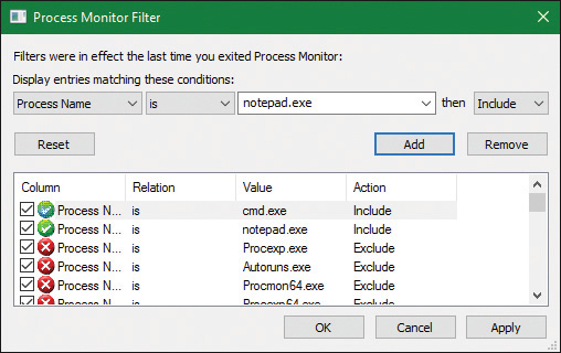
2. Make sure event logging is currently disabled (open the File and deselect Capture Events) and then start the command prompt.
3. Enable event logging (open the File menu and choose Event Logging, press Ctrl+E, or click the magnifying glass icon on the toolbar) and then type Notepad.exe and press Enter. On a typical Windows system, you should see anywhere between 500 and 3,500 events appear.
4. Stop capture and hide the Sequence and Time of Day columns so that you can focus your attention on the columns of interest. Your window should look similar to the one shown in the following screenshot.
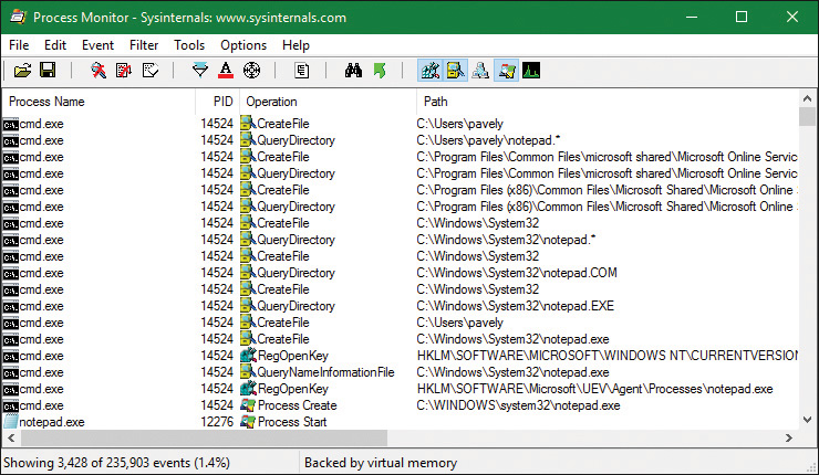
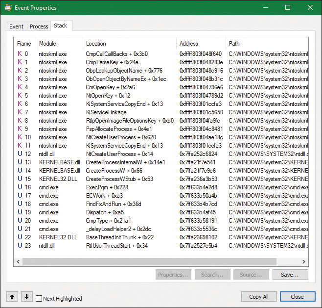
![]() A simple check for application-compatibility flags, which will let the user-mode process-creation code know if checks inside the application-compatibility database are required through the shim engine.
A simple check for application-compatibility flags, which will let the user-mode process-creation code know if checks inside the application-compatibility database are required through the shim engine.
![]() Multiple reads to SxS (search for Side-By-Side), Manifest, and MUI/Language keys, which are part of the assembly framework mentioned earlier.
Multiple reads to SxS (search for Side-By-Side), Manifest, and MUI/Language keys, which are part of the assembly framework mentioned earlier.
![]() File I/O to one or more .sdb files, which are the application-compatibility databases on the system. This I/O is where additional checks are done to see if the shim engine needs to be invoked for this application. Because Notepad is a well-behaved Microsoft program, it doesn’t require any shims.
File I/O to one or more .sdb files, which are the application-compatibility databases on the system. This I/O is where additional checks are done to see if the shim engine needs to be invoked for this application. Because Notepad is a well-behaved Microsoft program, it doesn’t require any shims.
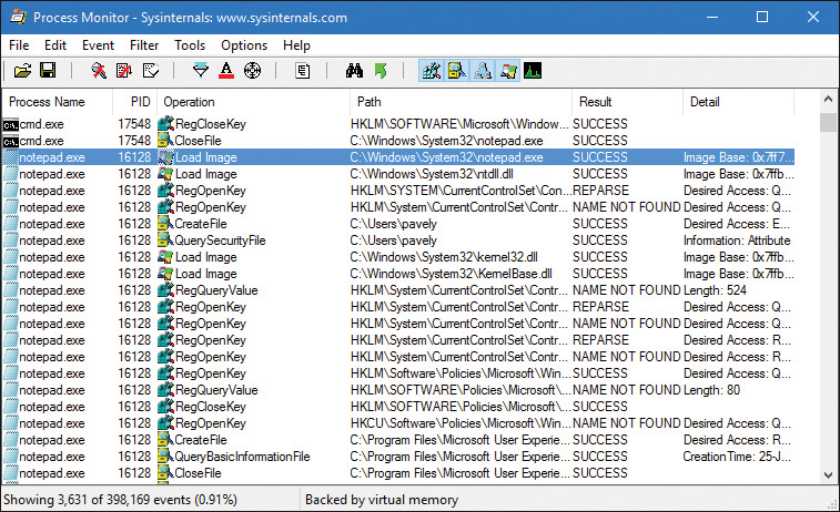
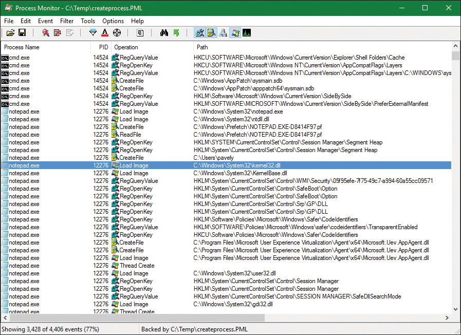
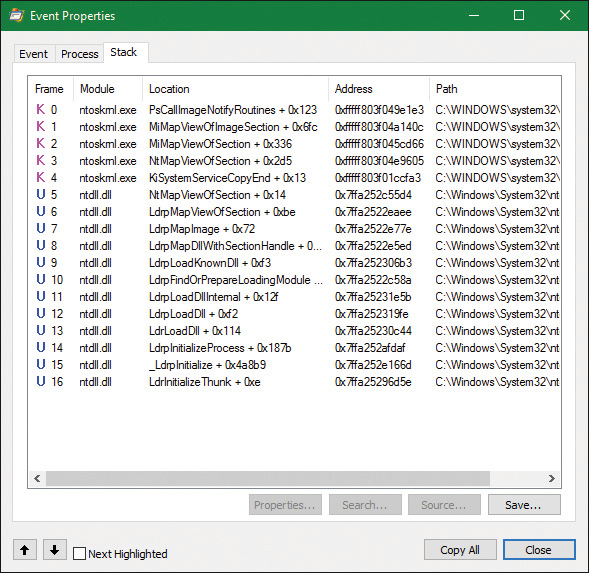
Terminating a process
A process is a container and a boundary. This means resources used by one process are not automatically visible in other processes, so some inter-process communication mechanism needs to be used to pass information between processes. Therefore, a process cannot accidentally write arbitrary bytes on
another process’s memory. That would require explicit call to a function such as WriteProcessMemory. However, to get that to work, a handle with the proper access mask (PROCESS_VM_WRITE) must be opened explicitly, which may or may not be granted. This natural isolation between processes also means that if some exception happens in one process, it will have no effect on other processes. The worst that can happen is that same process would crash, but the rest of the system stays intact.
A process can exit gracefully by calling the ExitProcess function. For many processes—depending
on linker settings—the process startup code for the first thread calls ExitProcess on the process’s behalf when the thread returns from its main function. The term gracefully means that DLLs loaded into the process get a chance to do some work by getting notified of the process exit using a call to their DllMain function with DLL_PROCESS_DETACH.
ExitProcess can be called only by the process itself asking to exit. An ungraceful termination of a process is possible using the TerminateProcess function, which can be called from outside the process. (For example, Process Explorer and Task Manager use it when so requested.) TerminateProcess requires a handle to the process that is opened with the PROCESS_TERMINATE access mask, which may or may not be granted. This is why it’s not easy (or it’s impossible) to terminate some processes (for example, Csrss)—the handle with the required access mask cannot be obtained by the requesting user. The meaning of ungraceful here is that DLLs don’t get a chance to execute code (DLL_PROCESS_DETACH
is not sent) and all threads are terminated abruptly. This can lead to data loss in some cases—for example, if a file cache has no chance to flush its data to the target file.
In whatever way a process ceases to exist, there can never be any leaks. That is, all process’s private memory is freed automatically by the kernel, the address space is destroyed, all handles to kernel objects are closed, etc. If open handles to the process still exist (the EPROCESS structure still exists), then other processes can still gain access to some process-management information, such as the process exit code (GetExitCodeProcess). Once these handles are closed, the EPROCESS is properly destroyed, and there’s truly nothing left of the process.
That being said, if third party drivers make allocations in kernel memory on behalf of a process—say, due to an IOCTL or merely due to a process notification—it is their responsibility to free any such pool memory on their own. Windows does not track or clean-up process-owned kernel memory (except for memory occupied by objects due to handles that the process created). This would typically be done through the IRP_MJ_CLOSE or IRP_MJ_CLEANUP notification to tell the driver that the handle to the device object has been closed, or through a process termination notification. (see Chapter 6, “I/O system,” for more on IOCTLs.)
Image loader
As we’ve just seen, when a process is started on the system, the kernel creates a process object to represent it and performs various kernel-related initialization tasks. However, these tasks do not result in the execution of the application, merely in the preparation of its context and environment. In fact, unlike drivers, which are kernel-mode code, applications execute in user mode. So most of the actual initialization work is done outside the kernel. This work is performed by the image loader, also internally referred to as Ldr.
The image loader lives in the user-mode system DLL Ntdll.dll and not in the kernel library. Therefore, it behaves just like standard code that is part of a DLL, and it is subject to the same restrictions in terms of memory access and security rights. What makes this code special is the guarantee that it will always be present in the running process (Ntdll.dll is always loaded) and that it is the first piece of code to run in user mode as part of a new process.
Because the loader runs before the actual application code, it is usually invisible to users and developers. Additionally, although the loader’s initialization tasks are hidden, a program typically does interact with its interfaces during the run time of a program—for example, whenever loading or unloading a DLL or querying the base address of one. Some of the main tasks the loader is responsible for include:
![]() Initializing the user-mode state for the application, such as creating the initial heap and setting up the thread-local storage (TLS) and fiber-local storage (FLS) slots.
Initializing the user-mode state for the application, such as creating the initial heap and setting up the thread-local storage (TLS) and fiber-local storage (FLS) slots.
![]() Parsing the import table (IAT) of the application to look for all DLLs that it requires (and then recursively parsing the IAT of each DLL), followed by parsing the export table of the DLLs to make sure the function is actually present. (Special forwarder entries can also redirect an export to yet another DLL.)
Parsing the import table (IAT) of the application to look for all DLLs that it requires (and then recursively parsing the IAT of each DLL), followed by parsing the export table of the DLLs to make sure the function is actually present. (Special forwarder entries can also redirect an export to yet another DLL.)
![]() Loading and unloading DLLs at run time, as well as on demand, and maintaining a list of all loaded modules (the module database).
Loading and unloading DLLs at run time, as well as on demand, and maintaining a list of all loaded modules (the module database).
![]() Handling manifest files, needed for Windows Side-by-Side (SxS) support, as well as Multiple Language User Interface (MUI) files and resources.
Handling manifest files, needed for Windows Side-by-Side (SxS) support, as well as Multiple Language User Interface (MUI) files and resources.
![]() Reading the application compatibility database for any shims, and loading the shim engine DLL if required.
Reading the application compatibility database for any shims, and loading the shim engine DLL if required.
![]() Enabling support for API Sets and API redirection, a core part of the One Core functionality that allows creating Universal Windows Platform (UWP) applications.
Enabling support for API Sets and API redirection, a core part of the One Core functionality that allows creating Universal Windows Platform (UWP) applications.
![]() Enabling dynamic runtime compatibility mitigations through the SwitchBack mechanism as well as interfacing with the shim engine and Application Verifier mechanisms.
Enabling dynamic runtime compatibility mitigations through the SwitchBack mechanism as well as interfacing with the shim engine and Application Verifier mechanisms.
As you can see, most of these tasks are critical to enabling an application to actually run its code. Without them, everything from calling external functions to using the heap would immediately fail. After the process has been created, the loader calls the NtContinue special native API to continue execution based on an exception frame located on the stack, just as an exception handler would. This exception frame, built by the kernel as we saw in an earlier section, contains the actual entry point of the application. Therefore, because the loader doesn’t use a standard call or jump into the running application, you’ll never see the loader initialization functions as part of the call tree in a stack trace for a thread.
Early process initialization
Because the loader is present in Ntdll.dll, which is a native DLL that’s not associated with any particular subsystem, all processes are subject to the same loader behavior (with some minor differences). Earlier, we took a detailed look at the steps that lead to the creation of a process in kernel mode, as well as some of the work performed by the Windows function CreateProcess. Here, we’ll cover all the other work that takes place in user mode, independent of any subsystem, as soon as the first user-mode instruction starts execution.
When a process starts, the loader performs the following steps:
1. It checks if LdrpProcessInitialized is already set to 1 or if the SkipLoaderInit flag is set in the TEB. In this case, skip all initialization and wait three seconds for someone to call LdrpProcess-InitializationComplete. This is used in cases where process reflection is used by Windows Error Reporting, or other process fork attempts where loader initialization is not needed.
2. It sets the LdrInitState to 0, meaning that the loader is uninitialized. Also set the PEB’s ProcessInitializing flag to 1 and the TEB’s RanProcessInit to 1.
3. It initializes the loader lock in the PEB.
4. It initializes the dynamic function table, used for unwind/exception support in JIT code.
5. It initializes the Mutable Read Only Heap Section (MRDATA), which is used to store security- relevant global variables that should not be modified by exploits (see Chapter 7 for more information).
6. It initializes the loader database in the PEB.
7. It initializes the National Language Support (NLS, for internationalization) tables for the process.
8. It builds the image path name for the application.
9. It captures the SEH exception handlers from the .pdata section and builds the internal exception tables.
10. It captures the system call thunks for the five critical loader functions: NtCreateSection, NtOpenFile, NtQueryAttributesFile, NtOpenSection, and NtMapViewOfSection.
11. It reads the mitigation options for the application (which are passed in by the kernel through the LdrSystemDllInitBlock exported variable). These are described in more detail in Chapter 7.
12. It queries the Image File Execution Options (IFEO) registry key for the application. This will include options such as the global flags (stored in GlobalFlags), as well as heap-debugging options (DisableHeapLookaside, ShutdownFlags, and FrontEndHeapDebugOptions), loader settings (UnloadEventTraceDepth, MaxLoaderThreads, UseImpersonatedDeviceMap), ETW settings (TracingFlags). Other options include MinimumStackCommitInBytes and MaxDeadActivationContexts. As part of this work, the Application Verifier package and related Verifier DLLs will be initialized and Control Flow Guard (CFG) options will be read from CFGOptions.
13. It looks inside the executable’s header to see whether it is a .NET application (specified by the presence of a .NET-specific image directory) and if it’s a 32-bit image. It also queries the kernel to verify if this is a Wow64 process. If needed, it handles a 32-bit IL-only image, which does not require Wow64.
14. It loads any configuration options specified in the executable’s Image Load Configuration Directory. These options, which a developer can define when compiling the application, and which the compiler and linker also use to implement certain security and mitigation features such as CFG, control the behavior of the executable.
15. It minimally initializes FLS and TLS.
16. It sets up debugging options for critical sections, creates the user-mode stack trace database if the appropriate global flag was enabled, and queries StrackTraceDatabaseSizeInMb from the Image File Execution Options.
17. It initializes the heap manager for the process and creates the first process heap. This will use various load configuration, image file execution, global flags, and executable header options to set up the required parameters.
18. It enables the Terminate process on heap corruption mitigation if it’s turned on.
19. It initializes the exception dispatch log if the appropriate global flag has enabled this.
20. It initializes the thread pool package, which supports the Thread Pool API. This queries and takes into account NUMA information.
21. It initializes and converts the environment block and parameter block, especially as needed to support WoW64 processes.
22. It opens the \KnownDlls object directory and builds the known DLL path. For a Wow64 process, \KnownDlls32 is used instead.
23. For store applications, it reads the Application Model Policy options, which are encoded in the WIN://PKG and WP://SKUID claims of the token (see the “AppContainers” section in Chapter 7 for more information).
24. It determines the process’s current directory, system path, and default load path (used when loading images and opening files), as well as the rules around default DLL search order. This includes reading the current policy settings for Universal (UWP) versus Desktop Bridge (Centennial) versus Silverlight (Windows Phone 8) packaged applications (or services).
25. It builds the first loader data table entry for Ntdll.dll and inserts it into the module database.
26. It builds the unwind history table.
27. It initializes the parallel loader, which is used to load all the dependencies (which don’t have cross-dependencies) using the thread pool and concurrent threads.
28. It builds the next loader data table entry for the main executable and inserts it into the module database.
29. If needed, it relocates the main executable image.
30. If enabled, it initializes Application Verifier.
31. It initializes the Wow64 engine if this is a Wow64 process. In this case, the 64-bit loader will finish its initialization, and the 32-bit loader will take control and re-start most of the operations we’ve just described up until this point.
32. If this is a .NET image, it validates it, loads Mscoree.dll (.NET runtime shim), and retrieves the main executable entry point (_CorExeMain), overwriting the exception record to set this as the entry point instead of the regular main function.
33. It initializes the TLS slots of the process.
34. For Windows subsystem applications, it manually loads Kernel32.dll and Kernelbase.dll, regardless of actual imports of the process. As needed, it uses these libraries to initialize the SRP/Safer (Software Restriction Policies) mechanisms, as well as capture the Windows subsystem thread initialization thunk function. Finally, it resolves any API Set dependencies that exist specifically between these two libraries.
35. It initializes the shim engine and parses the shim database.
36. It enables the parallel image loader, as long as the core loader functions scanned earlier do not have any system call hooks or “detours” attached to them, and based on the number of loader threads that have been configured through policy and image file execution options.
37. It sets the LdrInitState variable to 1, meaning “import loading in progress.”
At this point, the image loader is ready to start parsing the import table of the executable belonging to the application and start loading any DLLs that were dynamically linked during the compilation of the application. This will happen both for .NET images, which will have their imports processed by calling into the .NET runtime, as well as for regular images. Because each imported DLL can also have its own import table, this operation, in the past, continued recursively until all DLLs had been satisfied and all functions to be imported have been found. As each DLL was loaded, the loader kept state information for it and built the module database.
In newer versions of Windows, the loader instead builds a dependency map ahead of time, with specific nodes that describe a single DLL and its dependency graph, building out separate nodes that can be loaded in parallel. At various points when serialization is needed, the thread pool worker queue is “drained,” which services as a synchronization point. One such point is before calling all the DLL initialization routines of all the static imports, which is one of the last stages of the loader. Once this is done, all the static TLS initializers are called. Finally, for Windows applications, in between these two steps, the Kernel32 thread initialization thunk function (BaseThreadInitThunk) is called at the beginning, and the Kernel32 post-process initialization routine is called at the end.
DLL name resolution and redirection
Name resolution is the process by which the system converts the name of a PE-format binary to a physical file in situations where the caller has not specified or cannot specify a unique file identity. Because the locations of various directories (the application directory, the system directory, and so on) cannot be hardcoded at link time, this includes the resolution of all binary dependencies as well as LoadLibrary operations in which the caller does not specify a full path.
When resolving binary dependencies, the basic Windows application model locates files in a search path—a list of locations that is searched sequentially for a file with a matching base name—although various system components override the search path mechanism in order to extend the default application model. The notion of a search path is a holdover from the era of the command line, when an application’s current directory was a meaningful notion; this is somewhat anachronistic for modern GUI applications.
However, the placement of the current directory in this ordering allowed load operations on system binaries to be overridden by placing malicious binaries with the same base name in the application’s current directory, a technique often known as binary planting. To prevent security risks associated with this behavior, a feature known as safe DLL search mode was added to the path search computation and is enabled by default for all processes. Under safe search mode, the current directory is moved behind the three system directories, resulting in the following path ordering:
1. The directory from which the application was launched
2. The native Windows system directory (for example, C:\Windows\System32)
3. The 16-bit Windows system directory (for example, C:\Windows\System)
4. The Windows directory (for example, C:\Windows)
5. The current directory at application launch time
6. Any directories specified by the %PATH% environment variable
The DLL search path is recomputed for each subsequent DLL load operation. The algorithm used to compute the search path is the same as the one used to compute the default search path, but the application can change specific path elements by editing the %PATH% variable using the SetEnvironmentVariable API, changing the current directory using the SetCurrentDirectory API, or using the SetDllDirectory API to specify a DLL directory for the process. When a DLL directory is specified, the directory replaces the current directory in the search path and the loader ignores the safe DLL search mode setting for the process.
Callers can also modify the DLL search path for specific load operations by supplying the LOAD_WITH_ALTERED_SEARCH_PATH flag to the LoadLibraryEx API. When this flag is supplied and the DLL name supplied to the API specifies a full path string, the path containing the DLL file is used in place of the application directory when computing the search path for the operation. Note that if the path is a relative path, this behavior is undefined and potentially dangerous. When Desktop Bridge (Centennial) applications load, this flag is ignored.
Other flags that applications can specify to LoadLibraryEx include LOAD_LIBRARY_SEARCH_DLL_LOAD_DIR, LOAD_LIBRARY_SEARCH_APPLICATION_DIR, LOAD_LIBRARY_SEARCH_SYSTEM32, and LOAD_LIBRARY_SEARCH_USER_DIRS, in place of the LOAD_WITH_ALTERED_SEARCH_PATH flag. Each of these modifies the search order to only search the specific directory (or directories) that the flag references, or the flags can be combined as desired to search multiple locations. For example, combining the application, system32, and user directories results in LOAD_LIBRARY_SEARCH_DEFAULT_DIRS. Furthermore, these flags can be globally set using the SetDefaultDllDirectories API, which will affect all library loads from that point on.
Another way search-path ordering can be affected is if the application is a packaged application or if it is not a packaged service or legacy Silverlight 8.0 Windows Phone application. In these conditions, the DLL search order will not use the traditional mechanism and APIs, but will rather be restricted to the package-based graph search. This is also the case when the LoadPackagedLibrary API is used instead of the regular LoadLibraryEx function. The package-based graph is computed based on the <PackageDependency> entries in the UWP application’s manifest file’s <Dependencies> section, and guarantees that no arbitrary DLLs can accidentally load in the package.
Additionally, when a packaged application is loaded, as long as it is not a Desktop Bridge application, all application-configurable DLL search path ordering APIs, such as the ones we saw earlier, will be disabled, and only the default system behavior will be used (in combination with only looking through package dependencies for most UWP applications as per the above).
Unfortunately, even with safe search mode and the default path searching algorithms for legacy applications, which always include the application directory first, a binary might still be copied from its usual location to a user-accessible location (for example, from c:\windows\system32\notepad.exe into c:\temp\notepad.exe, an operation that does not require administrative rights). In this situation, an attacker can place a specifically crafted DLL in the same directory as the application, and due to the ordering above, it will take precedence over the system DLL. This can then be used for persistence or otherwise affecting the application, which might be privileged (especially if the user, unaware of the change, is elevating it through UAC). To defend against this, processes and/or administrators can use a process-mitigation policy (see Chapter 7 for more information on these) called Prefer System32 Images, which inverts the order above between points 1 and 2, as the name suggests.
DLL name redirection
Before attempting to resolve a DLL name string to a file, the loader attempts to apply DLL name redirection rules. These redirection rules are used to extend or override portions of the DLL namespace—which normally corresponds to the Win32 file system namespace—to extend the Windows application model. In order of application, these are:
![]() MinWin API Set redirection The API set mechanism is designed to allow different versions or editions of Windows to change the binary that exports a given system API in a manner that is transparent to applications, by introducing the concept of contracts. This mechanism was briefly touched upon in Chapter 2, and will be further explained in a later section.
MinWin API Set redirection The API set mechanism is designed to allow different versions or editions of Windows to change the binary that exports a given system API in a manner that is transparent to applications, by introducing the concept of contracts. This mechanism was briefly touched upon in Chapter 2, and will be further explained in a later section.
![]() .LOCAL redirection The .LOCAL redirection mechanism allows applications to redirect all loads of a specific DLL base name, regardless of whether a full path is specified, to a local copy of the DLL in the application directory—either by creating a copy of the DLL with the same base name followed by .local (for example, MyLibrary.dll.local) or by creating a file folder with the name .local under the application directory and placing a copy of the local DLL in the folder (for example, C:\\MyApp\.LOCAL\MyLibrary.dll). DLLs redirected by the .LOCAL mechanism are handled identically to those redirected by SxS. (See the next bullet point.) The loader honors .LOCAL redirection of DLLs only when the executable does not have an associated manifest, either embedded or external. It’s not enabled by default. To enable it globally, add the DWORD value
.LOCAL redirection The .LOCAL redirection mechanism allows applications to redirect all loads of a specific DLL base name, regardless of whether a full path is specified, to a local copy of the DLL in the application directory—either by creating a copy of the DLL with the same base name followed by .local (for example, MyLibrary.dll.local) or by creating a file folder with the name .local under the application directory and placing a copy of the local DLL in the folder (for example, C:\\MyApp\.LOCAL\MyLibrary.dll). DLLs redirected by the .LOCAL mechanism are handled identically to those redirected by SxS. (See the next bullet point.) The loader honors .LOCAL redirection of DLLs only when the executable does not have an associated manifest, either embedded or external. It’s not enabled by default. To enable it globally, add the DWORD value DevOverrideEnable in the base IFEO key (HKLM\Software\Microsoft\WindowsNT\CurrentVersion\Image File Execution Options) and set it to 1.
![]() Fusion (SxS) redirection Fusion (also referred to as side-by-side, or SxS) is an extension to the Windows application model that allows components to express more detailed binary dependency information (usually versioning information) by embedding binary resources known as manifests. The Fusion mechanism was first used so that applications could load the correct version of the Windows common controls package (comctl32.dll) after that binary was split into different versions that could be installed alongside one another; other binaries have since been versioned in the same fashion. As of Visual Studio 2005, applications built with the Microsoft linker use Fusion to locate the appropriate version of the C runtime libraries, while Visual Studio 2015 and later use API Set redirection to implement the idea of the universal CRT.
Fusion (SxS) redirection Fusion (also referred to as side-by-side, or SxS) is an extension to the Windows application model that allows components to express more detailed binary dependency information (usually versioning information) by embedding binary resources known as manifests. The Fusion mechanism was first used so that applications could load the correct version of the Windows common controls package (comctl32.dll) after that binary was split into different versions that could be installed alongside one another; other binaries have since been versioned in the same fashion. As of Visual Studio 2005, applications built with the Microsoft linker use Fusion to locate the appropriate version of the C runtime libraries, while Visual Studio 2015 and later use API Set redirection to implement the idea of the universal CRT.
The Fusion runtime tool reads embedded dependency information from a binary’s resource section using the Windows resource loader, and it packages the dependency information into lookup structures known as activation contexts. The system creates default activation contexts at the system and process level at boot and process startup time, respectively; in addition, each thread has an associated activation context stack, with the activation context structure at the top of the stack considered active. The per-thread activation context stack is managed both explicitly, via the ActivateActCtx and DeactivateActCtx APIs, and implicitly by the system at certain points, such as when the DLL main routine of a binary with embedded dependency information is called. When a Fusion DLL name redirection lookup occurs, the system searches for redirection information in the activation context at the head of the thread’s activation context stack, followed by the process and system activation contexts; if redirection information is present, the file identity specified by the activation context is used for the load operation.
![]() Known DLL redirection Known DLLs is a mechanism that maps specific DLL base names to files in the system directory, preventing the DLL from being replaced with an alternate version in a different location.
Known DLL redirection Known DLLs is a mechanism that maps specific DLL base names to files in the system directory, preventing the DLL from being replaced with an alternate version in a different location.
One edge case in the DLL path search algorithm is the DLL versioning check performed on 64-bit and WoW64 applications. If a DLL with a matching base name is located but is subsequently determined to have been compiled for the wrong machine architecture—for example, a 64-bit image in a 32-bit application—the loader ignores the error and resumes the path search operation, starting with the path element after the one used to locate the incorrect file. This behavior is designed to allow applications to specify both 64-bit and 32-bit entries in the global %PATH% environment variable.
EXPERIMENT: Observing DLL load search order
1. If the OneDrive is running, close it from its tray icon. Make sure to close all Explorer windows that are looking at OneDrive content.
2. Open Process Monitor and add filters to show just the process OneDrive.exe. Optionally, show only the operation for CreateFile.
3. Go to %LocalAppData%\Microsoft\OneDrive and launch OneDrive.exe or OneDrive Personal.cmd (which launches OneDrive.exe as “personal” rather than “business”). You should see something like the following (note that OneDrive is a 32 bit process, here running on a 64 bit system):
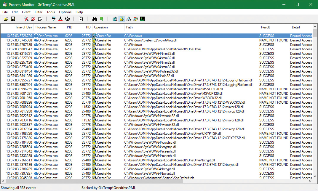
![]() KnownDlls DLLs load from the system location (ole32.dll in the screenshot).
KnownDlls DLLs load from the system location (ole32.dll in the screenshot).
![]() LoggingPlatform.Dll is loaded from a version subdirectory, probably because OneDrive calls SetDllDirectory to redirect searches to the latest version (17.3.6743.1212 in the screenshot).
LoggingPlatform.Dll is loaded from a version subdirectory, probably because OneDrive calls SetDllDirectory to redirect searches to the latest version (17.3.6743.1212 in the screenshot).
![]() The MSVCR120.dll (MSVC run time version 12) is searched for in the executable’s directory, and is not found. Then it’s searched in the version subdirectory, where it’s located.
The MSVCR120.dll (MSVC run time version 12) is searched for in the executable’s directory, and is not found. Then it’s searched in the version subdirectory, where it’s located.
![]() The Wsock32.Dll (WinSock) is searched in the executable’s path, then in the version subdirectory, and finally located in the system directory (SysWow64). Note that this DLL is not a KnownDll.
The Wsock32.Dll (WinSock) is searched in the executable’s path, then in the version subdirectory, and finally located in the system directory (SysWow64). Note that this DLL is not a KnownDll.
Loaded module database
The loader maintains a list of all modules (DLLs as well as the primary executable) that have been loaded by a process. This information is stored in the PEB—namely, in a substructure identified by Ldr and called PEB_LDR_DATA. In the structure, the loader maintains three doubly linked lists, all containing the same information but ordered differently (either by load order, memory location, or initialization order). These lists contain structures called loader data table entries (LDR_DATA_TABLE_ENTRY) that store information about each module.
Additionally, because lookups in linked lists are algorithmically expensive (being done in linear time), the loader also maintains two red-black trees, which are efficient binary lookup trees. The first is sorted by base address, while the second is sorted by the hash of the module’s name. With these trees, the searching algorithm can run in logarithmic time, which is significantly more efficient and greatly speeds up process-creation performance in Windows 8 and later. Additionally, as a security precaution, the root of these two trees, unlike the linked lists, is not accessible in the PEB. This makes them harder to locate by shell code, which is operating in an environment where address space layout randomization (ASLR) is enabled. (See Chapter 5 for more on ASLR.)
Table 3-9 lists the various pieces of information the loader maintains in an entry.
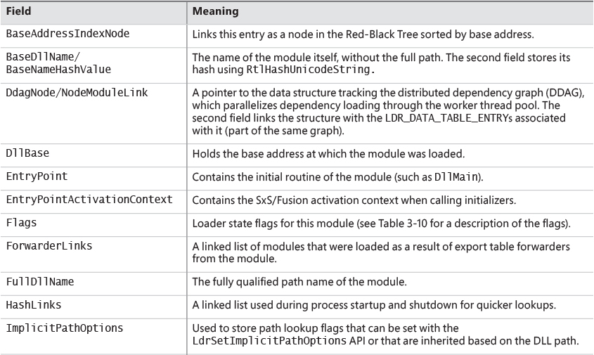
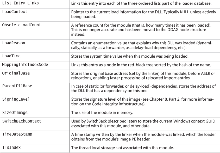
One way to look at a process’s loader database is to use WinDbg and its formatted output of the PEB. The next experiment shows you how to do this and how to look at the LDR_DATA_TABLE_ENTRY structures on your own.
Although this section covers the user-mode loader in Ntdll.dll, note that the kernel also employs its own loader for drivers and dependent DLLs, with a similar loader entry structure called KLDR_DATA_TABLE_ENTRY instead. Likewise, the kernel-mode loader has its own database of such entries, which is directly accessible through the PsLoadedModuleList global data variable. To dump the kernel’s loaded module database, you can use a similar !list command as shown in the preceding experiment by replacing the pointer at the end of the command with nt! PsLoadedModuleList and using the new structure/module name: !list -x " dt nt!_kldr_data_table_entry" nt!PsLoadedModuleList.
Looking at the list in this raw format gives you some extra insight into the loader’s internals, such as the Flags field, which contains state information that !peb on its own would not show you. See Table 3-10 for their meaning. Because both the kernel and user-mode loaders use this structure, the meaning of the flags is not always the same. In this table, we explicitly cover the user-mode flags only (some of which may exist in the kernel structure as well).
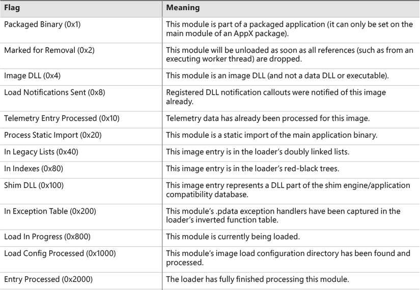
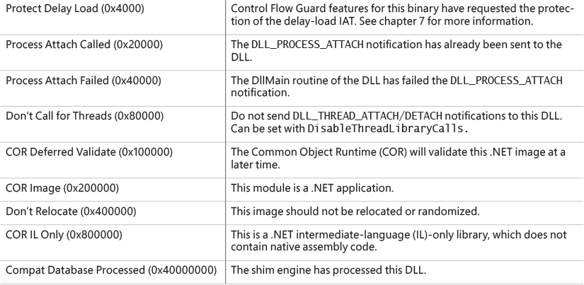
Import parsing
Now that we’ve explained the way the loader keeps track of all the modules loaded for a process, you can continue analyzing the startup initialization tasks performed by the loader. During this step, the loader will do the following:
1. Load each DLL referenced in the import table of the process’s executable image.
2. Check whether the DLL has already been loaded by checking the module database. If it doesn’t find it in the list, the loader opens the DLL and maps it into memory.
3. During the mapping operation, the loader first looks at the various paths where it should attempt to find this DLL, as well as whether this DLL is a known DLL, meaning that the system has already loaded it at startup and provided a global memory mapped file for accessing it. Certain deviations from the standard lookup algorithm can also occur, either through the use of a .local file (which forces the loader to use DLLs in the local path) or through a manifest file, which can specify a redirected DLL to use to guarantee a specific version.
4. After the DLL has been found on disk and mapped, the loader checks whether the kernel has loaded it somewhere else—this is called relocation. If the loader detects relocation, it parses the relocation information in the DLL and performs the operations required. If no relocation information is present, DLL loading fails.
5. The loader then creates a loader data table entry for this DLL and inserts it into the database.
6. After a DLL has been mapped, the process is repeated for this DLL to parse its import table and all its dependencies.
7. After each DLL is loaded, the loader parses the IAT to look for specific functions that are being imported. Usually this is done by name, but it can also be done by ordinal (an index number). For each name, the loader parses the export table of the imported DLL and tries to locate a match. If no match is found, the operation is aborted.
8. The import table of an image can also be bound. This means that at link time, the developers already assigned static addresses pointing to imported functions in external DLLs. This removes the need to do the lookup for each name, but it assumes that the DLLs the application will use will always be located at the same address. Because Windows uses address space randomization (see Chapter 5 for more information on ASLR), this is usually not the case for system applications and libraries.
9. The export table of an imported DLL can use a forwarder entry, meaning that the actual function is implemented in another DLL. This must essentially be treated like an import or dependency, so after parsing the export table, each DLL referenced by a forwarder is also loaded and the loader goes back to step 1.
After all imported DLLs (and their own dependencies, or imports) have been loaded, all the required imported functions have been looked up and found, and all forwarders also have been loaded and processed, the step is complete: All dependencies that were defined at compile time by the application and its various DLLs have now been fulfilled. During execution, delayed dependencies (called delay load), as well as run-time operations (such as calling LoadLibrary) can call into the loader and essentially repeat the same tasks. Note, however, that a failure in these steps will result in an error launching the application if they are done during process startup. For example, attempting to run an application that requires a function that isn’t present in the current version of the operating system can result in a message similar to the one in Figure 3-12.
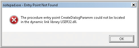
Post-import process initialization
After the required dependencies have been loaded, several initialization tasks must be performed to fully finalize launching the application. In this phase, the loader will do the following:
1. These steps begin with the LdrInitState variable set to 2, which means imports have loaded.
2. The initial debugger breakpoint will be hit when using a debugger such as WinDbg. This is where you had to type g to continue execution in earlier experiments.
3. Check if this is a Windows subsystem application, in which case the BaseThreadInitThunk function should’ve been captured in the early process initialization steps. At this point, it is called and checked for success. Similarly, the TermsrvGetWindowsDirectoryW function, which should have been captured earlier (if on a system which supports terminal services), is now called, which resets the System and Windows directories path.
4. Using the distributed graph, recurse through all dependencies and run the initializers for all of the images’ static imports. This is the step that calls the DllMain routine for each DLL (allowing each DLL to perform its own initialization work, which might even include loading new DLLs at run time) as well as processes the TLS initializers of each DLL. This is one of the last steps in which loading an application can fail. If all the loaded DLLs do not return a successful return code after finishing their DllMain routines, the loader aborts starting the application.
5. If the image uses any TLS slots, call its TLS initializer.
6. Run the post-initialization shim engine callback if the module is being shimmed for application compatibility.
7. Run the associated subsystem DLL post-process initialization routine registered in the PEB. For Windows applications, this does Terminal Services–specific checks, for example.
8. At this point, write an ETW event indicating that the process has loaded successfully.
9. If there is a minimum stack commit, touch the thread stack to force an in-page of the committed pages.
10. Set LdrInitState to 3, which means initialization done. Set the PEB’s ProcessInitializing field back to 0. Then, update the LdrpProcessInitialized variable.
SwitchBack
As each new version of Windows fixes bugs such as race conditions and incorrect parameter validation checks in existing API functions, an application-compatibility risk is created for each change, no matter how minor. Windows makes use of a technology called SwitchBack, implemented in the loader, which enables software developers to embed a GUID specific to the Windows version they are targeting in their executable’s associated manifest.
For example, if a developer wants to take advantage of improvements added in Windows 10 to a given API, she would include the Windows 10 GUID in her manifest, while if a developer has a legacy application that depends on Windows 7–specific behavior, she would put the Windows 7 GUID in the manifest instead.
SwitchBack parses this information and correlates it with embedded information in SwitchBack-compatible DLLs (in the .sb_data image section) to decide which version of an affected API should be called by the module. Because SwitchBack works at the loaded-module level, it enables a process to have both legacy and current DLLs concurrently calling the same API, yet observing different results.
SwitchBack GUIDs
Windows currently defines GUIDs that represent compatibility settings for every version from Windows Vista:
![]() {e2011457-1546-43c5-a5fe-008deee3d3f0} for Windows Vista
{e2011457-1546-43c5-a5fe-008deee3d3f0} for Windows Vista
![]() {35138b9a-5d96-4fbd-8e2d-a2440225f93a} for Windows 7
{35138b9a-5d96-4fbd-8e2d-a2440225f93a} for Windows 7
![]() {4a2f28e3-53b9-4441-ba9c-d69d4a4a6e38} for Windows 8
{4a2f28e3-53b9-4441-ba9c-d69d4a4a6e38} for Windows 8
![]() {1f676c76-80e1-4239-95bb-83d0f6d0da78} for Windows 8.1
{1f676c76-80e1-4239-95bb-83d0f6d0da78} for Windows 8.1
![]() {8e0f7a12-bfb3-4fe8-b9a5-48fd50a15a9a} for Windows 10
{8e0f7a12-bfb3-4fe8-b9a5-48fd50a15a9a} for Windows 10
These GUIDs must be present in the application’s manifest file under the <SupportedOS> element in the ID attribute in a compatibility attribute entry. (If the application manifest does not contain a GUID, Windows Vista is chosen as the default compatibility mode.) Using Task Manager, you can enable an Operating System Context column in the Details tab, which will show if any applications are running with a specific OS context (an empty value usually means they are operating in Windows 10 mode). Figure 3-13 shows an example of a few such applications, which are operating in Windows Vista and Windows 7 modes, even on a Windows 10 system.
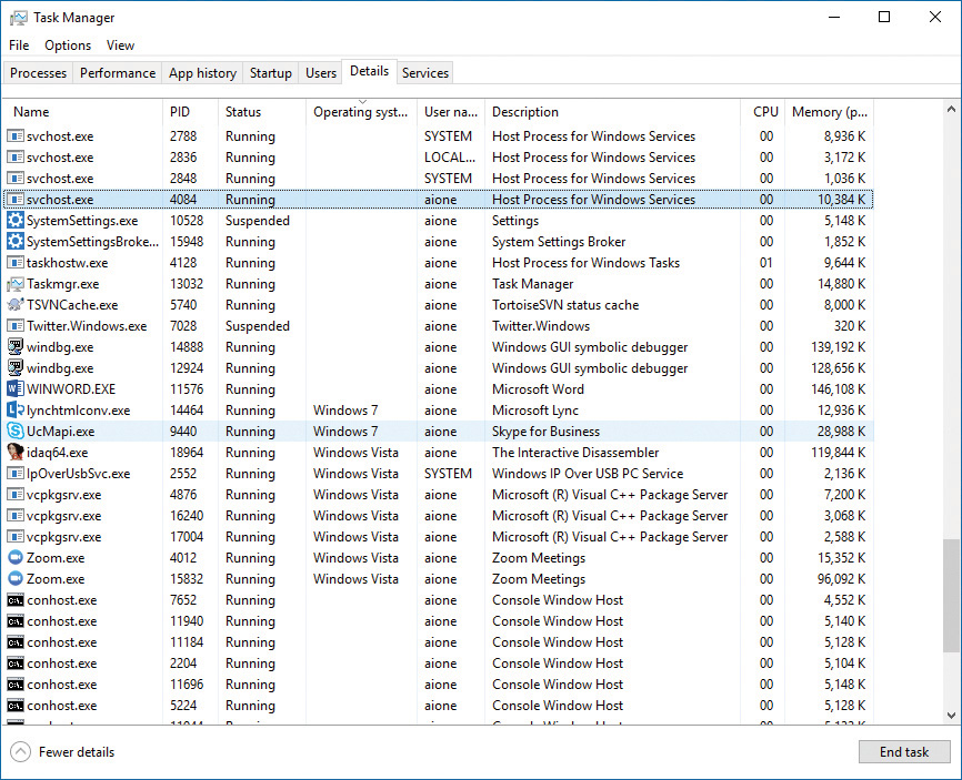
Here is an example of a manifest entry that sets compatibility for Windows 10:
<compatibility xmlns="urn:schemas-microsoft-com:compatibility.v1">
<application>
<!-- Windows 10 -->
<supportedOS Id="{8e0f7a12-bfb3-4fe8-b9a5-48fd50a15a9a}" />
</application>
</compatibility>
SwitchBack compatibility modes
As a few examples of what SwitchBack can do, here’s what running under the Windows 7 context affects:
![]() RPC components use the Windows thread pool instead of a private implementation.
RPC components use the Windows thread pool instead of a private implementation.
![]() DirectDraw Lock cannot be acquired on the primary buffer.
DirectDraw Lock cannot be acquired on the primary buffer.
![]() Blitting on the desktop is not allowed without a clipping window.
Blitting on the desktop is not allowed without a clipping window.
![]() A race condition in
A race condition in GetOverlappedResult is fixed.
![]() Calls to
Calls to CreateFile are allowed to pass a “downgrade” flag to receive exclusive open to a file even when the caller does not have write privilege, which causes NtCreateFile not to receive the FILE_DISALLOW_EXCLUSIVE flag.
Running in Windows 10 mode, on the other hand, subtly affects how the Low Fragmentation Heap (LFH) behaves, by forcing LFH sub-segments to be fully committed and padding all allocations with a header block unless the Windows 10 GUID is present. Additionally, in Windows 10, using the Raise Exception on Invalid Handle Close mitigation (see Chapter 7 for more information) will result in CloseHandle and RegCloseKey respecting the behavior. On the other hand, on previous operating systems, if the debugger is not attached, this behavior will be disabled before calling NtClose, and then re-enabled after the call.
As another example, the Spell Checking Facility will return NULL for languages which don’t have a spell checker, while it returns an “empty” spell checker on Windows 8.1. Similarly, the implementation of the function IShellLink::Resolve will return E_INVALIDARG when operating in Windows 8 compatibility mode when given a relative path, but will not contain this check in Windows 7 mode.
Furthermore, calls to GetVersionEx or the equivalent functions in NtDll such as RtlVerifyVersion- Info will return the maximum version number that corresponds to the SwitchBack Context GUID that was specified.
![]() Note
Note
These APIs have been deprecated, and calls to GetVersionEx will return 6.2 on all versions of Windows 8 and later if a higher SwitchBack GUID is not provided.
SwitchBack behavior
Whenever a Windows API is affected by changes that might break compatibility, the function’s entry code calls the SbSwitchProcedure to invoke the SwitchBack logic. It passes along a pointer to the SwitchBack module table, which contains information about the SwitchBack mechanisms employed in the module. The table also contains a pointer to an array of entries for each SwitchBack point. This table contains a description of each branch-point that identifies it with a symbolic name and a comprehensive description, along with an associated mitigation tag. Typically, there will be several branch-points in a module, one for Windows Vista behavior, one for Windows 7 behavior, etc.
For each branch-point, the required SwitchBack context is given—it is this context that determines which of the two (or more) branches is taken at runtime. Finally, each of these descriptors contains a function pointer to the actual code that each branch should execute. If the application is running with the Windows 10 GUID, this will be part of its SwitchBack context, and the SbSelectProcedure API, upon parsing the module table, will perform a match operation. It finds the module entry descriptor for the context and proceeds to call the function pointer included in the descriptor.
SwitchBack uses ETW to trace the selection of given SwitchBack contexts and branch-points and feeds the data into the Windows AIT (Application Impact Telemetry) logger. This data can be periodically collected by Microsoft to determine the extent to which each compatibility entry is being used, identify the applications using it (a full stack trace is provided in the log), and notify third-party vendors.
As mentioned, the compatibility level of the application is stored in its manifest. At load time, the loader parses the manifest file, creates a context data structure, and caches it in the pShimData member of the PEB. This context data contains the associated compatibility GUIDs that this process is executing under and determines which version of the branch-points in the called APIs that employ SwitchBack will be executed.
API Sets
While SwitchBack uses API redirection for specific application-compatibility scenarios, there is a much more pervasive redirection mechanism used in Windows for all applications, called API Sets. Its purpose is to enable fine-grained categorization of Windows APIs into sub-DLLs instead of having large multi-purpose DLLs that span nearly thousands of APIs that might not be needed on all types of Windows systems today and in the future. This technology, developed mainly to support the refactoring of the bottom-most layers of the Windows architecture to separate it from higher layers, goes hand in hand with the breakdown of Kernel32.dll and Advapi32.dll (among others) into multiple, virtual DLL files.
For example, Figure 3-14 shows a screenshot of Dependency Walker where Kernel32.dll, which is a core Windows library, imports from many other DLLs, beginning with API-MS-WIN. Each of these DLLs contains a small subset of the APIs that Kernel32 normally provides, but together they make up the entire API surface exposed by Kernel32.dll. The CORE-STRING library, for instance, provides only the Windows base string functions.
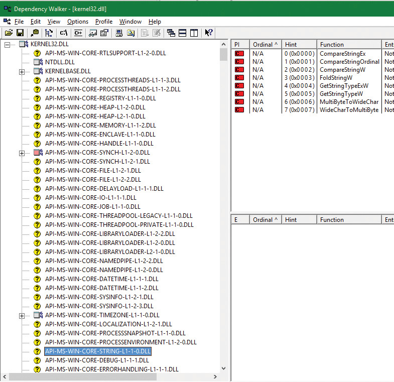
In splitting functions across discrete files, two objectives are achieved. First, doing this allows future applications to link only with the API libraries that provide the functionality that they need. Second, if Microsoft were to create a version of Windows that did not support, for example, localization (say, a non-user-facing, English-only embedded system), it would be possible to simply remove the sub-DLL and modify the API Set schema. This would result in a smaller Kernel32 binary, and any applications that ran without requiring localization would still run.
With this technology, a “base” Windows system called MinWin is defined (and, at the source level, built), with a minimum set of services that includes the kernel, core drivers (including file systems, basic system processes such as CSRSS and the Service Control Manager, and a handful of Windows services). Windows Embedded, with its Platform Builder, provides what might seem to be a similar technology, as system builders are able to remove select “Windows components,” such as the shell, or the network stack. However, removing components from Windows leaves dangling dependencies—code paths that, if exercised, would fail because they depend on the removed components. MinWin’s dependencies, on the other hand, are entirely self-contained.
When the process manager initializes, it calls the PspInitializeApiSetMap function, which is responsible for creating a section object of the API Set redirection table, which is stored in %SystemRoot%\System32\ApiSetSchema.dll. The DLL contains no executable code, but it has a section called .apiset that contains API Set mapping data that maps virtual API Set DLLs to logical DLLs that implement the APIs. Whenever a new process starts, the process manager maps the section object into the process’s address space and sets the ApiSetMap field in the process’s PEB to point to the base address where the section object was mapped.
In turn, the loader’s LdrpApplyFileNameRedirection function, which is normally responsible for the .local and SxS/Fusion manifest redirection that was mentioned earlier, also checks for API Set redirection data whenever a new import library that has a name starting with API- loads (either dynamically or statically). The API Set table is organized by library with each entry describing in which logical DLL the function can be found, and that DLL is what gets loaded. Although the schema data is a binary format, you can dump its strings with the Sysinternals Strings tool to see which DLLs are currently defined:
C:\Windows\System32>strings apisetschema.dll
...
api-ms-onecoreuap-print-render-l1-1-0
printrenderapihost.dllapi-ms-onecoreuap-settingsync-status-l1-1-0
settingsynccore.dll
api-ms-win-appmodel-identity-l1-2-0
kernel.appcore.dllapi-ms-win-appmodel-runtime-internal-l1-1-3
api-ms-win-appmodel-runtime-l1-1-2
api-ms-win-appmodel-state-l1-1-2
api-ms-win-appmodel-state-l1-2-0
api-ms-win-appmodel-unlock-l1-1-0
api-ms-win-base-bootconfig-l1-1-0
advapi32.dllapi-ms-win-base-util-l1-1-0
api-ms-win-composition-redirection-l1-1-0
...
api-ms-win-core-com-midlproxystub-l1-1-0
api-ms-win-core-com-private-l1-1-1
api-ms-win-core-comm-l1-1-0
api-ms-win-core-console-ansi-l2-1-0
api-ms-win-core-console-l1-1-0
api-ms-win-core-console-l2-1-0
api-ms-win-core-crt-l1-1-0
api-ms-win-core-crt-l2-1-0
api-ms-win-core-datetime-l1-1-2
api-ms-win-core-debug-l1-1-2
api-ms-win-core-debug-minidump-l1-1-0
...
api-ms-win-core-firmware-l1-1-0
api-ms-win-core-guard-l1-1-0
api-ms-win-core-handle-l1-1-0
api-ms-win-core-heap-l1-1-0
api-ms-win-core-heap-l1-2-0
api-ms-win-core-heap-l2-1-0
api-ms-win-core-heap-obsolete-l1-1-0
api-ms-win-core-interlocked-l1-1-1
api-ms-win-core-interlocked-l1-2-0
api-ms-win-core-io-l1-1-1
api-ms-win-core-job-l1-1-0
...
Jobs
A job is a nameable, securable, shareable kernel object that allows control of one or more processes as a group. A job object’s basic function is to allow groups of processes to be managed and manipulated as a unit. A process can be a member of any number of jobs, although the typical case is just one. A process’s association with a job object can’t be broken, and all processes created by the process and its descendants are associated with the same job object (unless child processes are created with the CREATE_BREAKAWAY_FROM_JOB flag and the job itself has not restricted it). The job object also records basic accounting information for all processes associated with the job and for all processes that were associated with the job but have since terminated.
Jobs can also be associated with an I/O completion port object, which other threads might be waiting for, with the Windows GetQueuedCompletionStatus function or by using the Thread Pool API (the native function TpAllocJobNotification). This allows interested parties (typically the job creator) to monitor for limit violations and events that could affect the job’s security, such as a new process being created or a process abnormally exiting.
Jobs play a significant role in a number of system mechanisms, enumerated here:
![]() They manage modern apps (UWP processes), as discussed in more detail in Chapter 9 in Part 2. In fact, every modern app is running under a job. You can verify this with Process Explorer, as described in the “Viewing the job object” experiment later in this chapter.
They manage modern apps (UWP processes), as discussed in more detail in Chapter 9 in Part 2. In fact, every modern app is running under a job. You can verify this with Process Explorer, as described in the “Viewing the job object” experiment later in this chapter.
![]() They are used to implement Windows Container support, through a mechanism called server silo, covered later in this section.
They are used to implement Windows Container support, through a mechanism called server silo, covered later in this section.
![]() They are the primary way through which the Desktop Activity Moderator (DAM) manages throttling, timer virtualization, timer freezing, and other idle-inducing behaviors for Win32 applications and services. The DAM is described in Chapter 8 in Part 2.
They are the primary way through which the Desktop Activity Moderator (DAM) manages throttling, timer virtualization, timer freezing, and other idle-inducing behaviors for Win32 applications and services. The DAM is described in Chapter 8 in Part 2.
![]() They allow the definition and management of scheduling groups for dynamic fair-share scheduling (DFSS), which is described in Chapter 4.
They allow the definition and management of scheduling groups for dynamic fair-share scheduling (DFSS), which is described in Chapter 4.
![]() They allow for the specification of a custom memory partition, which enables usage of the Memory Partitioning API described in Chapter 5.
They allow for the specification of a custom memory partition, which enables usage of the Memory Partitioning API described in Chapter 5.
![]() They serve as a key enabler for features such as Run As (Secondary Logon), Application Boxing, and Program Compatibility Assistant.
They serve as a key enabler for features such as Run As (Secondary Logon), Application Boxing, and Program Compatibility Assistant.
![]() They provide part of the security sandbox for applications such as Google Chrome and Microsoft Office Document Converter, as well as mitigation from denial-of-service (DoS) attacks through Windows Management Instrumentation (WMI) requests.
They provide part of the security sandbox for applications such as Google Chrome and Microsoft Office Document Converter, as well as mitigation from denial-of-service (DoS) attacks through Windows Management Instrumentation (WMI) requests.
Job limits
The following are some of the CPU-, memory-, and I/O-related limits you can specify for a job:
![]() Maximum number of active processes This limits the number of concurrently existing processes in the job. If this limit is reached, new processes that should be assigned to the job are blocked from creation.
Maximum number of active processes This limits the number of concurrently existing processes in the job. If this limit is reached, new processes that should be assigned to the job are blocked from creation.
![]() Job-wide user-mode CPU time limit This limits the maximum amount of user-mode CPU time that the processes in the job can consume (including processes that have run and exited). Once this limit is reached, by default all the processes in the job are terminated with an error code and no new processes can be created in the job (unless the limit is reset). The job object is signaled, so any threads waiting for the job will be released. You can change this default behavior with a call to
Job-wide user-mode CPU time limit This limits the maximum amount of user-mode CPU time that the processes in the job can consume (including processes that have run and exited). Once this limit is reached, by default all the processes in the job are terminated with an error code and no new processes can be created in the job (unless the limit is reset). The job object is signaled, so any threads waiting for the job will be released. You can change this default behavior with a call to SetInformationJobObject to set the EndOfJobTimeAction member of the JOBOBJECT_END_OF_JOB_TIME_INFORMATION structure passed with the JobObjectEndOfJobTimeInformation information class and request a notification to be sent through the job’s completion port instead.
![]() Per-process user-mode CPU time limit This allows each process in the job to accumulate only a fixed maximum amount of user-mode CPU time. When the maximum is reached, the process terminates (with no chance to clean up).
Per-process user-mode CPU time limit This allows each process in the job to accumulate only a fixed maximum amount of user-mode CPU time. When the maximum is reached, the process terminates (with no chance to clean up).
![]() Job processor affinity This sets the processor affinity mask for each process in the job. (Individual threads can alter their affinity to any subset of the job affinity, but processes can’t alter their process affinity setting.)
Job processor affinity This sets the processor affinity mask for each process in the job. (Individual threads can alter their affinity to any subset of the job affinity, but processes can’t alter their process affinity setting.)
![]() Job group affinity This sets a list of groups to which the processes in the job can be assigned. Any affinity changes are then subject to the group selection imposed by the limit. This is treated as a group-aware version of the job processor affinity limit (legacy), and prevents that limit from being used.
Job group affinity This sets a list of groups to which the processes in the job can be assigned. Any affinity changes are then subject to the group selection imposed by the limit. This is treated as a group-aware version of the job processor affinity limit (legacy), and prevents that limit from being used.
![]() Job process priority class This sets the priority class for each process in the job. Threads can’t increase their priority relative to the class (as they normally can). Attempts to increase thread priority are ignored. (No error is returned on calls to
Job process priority class This sets the priority class for each process in the job. Threads can’t increase their priority relative to the class (as they normally can). Attempts to increase thread priority are ignored. (No error is returned on calls to SetThreadPriority, but the increase doesn’t occur.)
![]() Default working set minimum and maximum This defines the specified working set minimum and maximum for each process in the job. (This setting isn’t job-wide. Each process has its own working set with the same minimum and maximum values.)
Default working set minimum and maximum This defines the specified working set minimum and maximum for each process in the job. (This setting isn’t job-wide. Each process has its own working set with the same minimum and maximum values.)
![]() Process and job committed virtual memory limit This defines the maximum amount of virtual address space that can be committed by either a single process or the entire job.
Process and job committed virtual memory limit This defines the maximum amount of virtual address space that can be committed by either a single process or the entire job.
![]() CPU rate control This defines the maximum amount of CPU time that the job is allowed to use before it will experience forced throttling. This is used as part of the scheduling group support described in Chapter 4.
CPU rate control This defines the maximum amount of CPU time that the job is allowed to use before it will experience forced throttling. This is used as part of the scheduling group support described in Chapter 4.
![]() Network bandwidth rate control This defines the maximum outgoing bandwidth for the entire job before throttling takes effect. It also enables setting a differentiated services code point (DSCP) tag for QoS purposes for each network packet sent by the job. This can only be set for one job in a hierarchy, and affects the job and any child jobs.
Network bandwidth rate control This defines the maximum outgoing bandwidth for the entire job before throttling takes effect. It also enables setting a differentiated services code point (DSCP) tag for QoS purposes for each network packet sent by the job. This can only be set for one job in a hierarchy, and affects the job and any child jobs.
![]() Disk I/O bandwidth rate control This is the same as network bandwidth rate control, but is applied to disk I/O instead, and can control either bandwidth itself or the number of I/O operations per second (IOPS). It can be set either for a particular volume or for all volumes on the system.
Disk I/O bandwidth rate control This is the same as network bandwidth rate control, but is applied to disk I/O instead, and can control either bandwidth itself or the number of I/O operations per second (IOPS). It can be set either for a particular volume or for all volumes on the system.
For many of these limits, the job owner can set specific thresholds, at which point a notification will be sent (or, if no notification is registered, the job will simply be killed). Additionally, rate controls allow for tolerance ranges and tolerance intervals—for example, allowing a process to go beyond 20 percent of its network bandwidth limit for up to 10 seconds every 5 minutes. These notifications are done by queuing an appropriate message to the I/O completion port for the job. (See the Windows SDK documentation for the details.)
Finally, you can place user-interface limits on processes in a job. Such limits include restricting processes from opening handles to windows owned by threads outside the job, reading and/or writing to the clipboard, and changing the many user-interface system parameters via the Windows SystemParametersInfo function. These user-interface limits are managed by the Windows subsystem GDI/USER driver, Win32k.sys, and are enforced through one of the special callouts that it registers with the process manager, the job callout. You can grant access for all processes in a job to specific user handles (for example, window handle) by calling the UserHandleGrantAccess function; this can only be called by a process that is not part of the job in question (naturally).
Working with a job
A job object is created using the CreateJobObject API. The job is initially created empty of any process. To add a process to a job, call the AssignProcessToJobObject, which can be called multiple times to add processes to the job or even to add the same process to multiple jobs. This last option creates a nested job, described in the next section. Another way to add a process to a job is to manually specify a handle to the job object by using the PS_CP_JOB_LIST process-creation attribute described earlier in this chapter. One or more handles to job objects can be specified, which will all be joined.
The most interesting API for jobs is SetInformationJobObject, which allows the setting of the various limits and settings mentioned in the previous section, and contains internal information classes used by mechanisms such as Containers (Silo), the DAM, or Windows UWP applications. These values can be read back with QueryInformationJobObject, which can provide interested parties with the limits set on a job. It’s also necessary to call in case limit notifications have been set (as described in the previous section) in order for the caller to know precisely which limits were violated. Another sometimes-useful function is TerminateJobObject, which terminates all processes in the job (as if TerminateProcess were called on each process).
Nested jobs
Until Windows 7 and Windows Server 2008 R2, a process could only be associated with a single job, which made jobs less useful than they could be, as in some cases an application could not know in advance whether a process it needed to manage happened to be in a job or not. Starting with Windows 8 and Windows Server 2012, a process can be associated with multiple jobs, effectively creating a job hierarchy.
A child job holds a subset of processes of its parent job. Once a process is added to more than one job, the system tries to form a hierarchy, if possible. A current restriction is that jobs cannot form a hierarchy if any of them sets any UI limits (SetInformationJobObject with JobObjectBasicUIRestrictions argument).
Job limits for a child job cannot be more permissive than its parent, but they can be more restrictive. For example, if a parent job sets a memory limit of 100 MB for the job, any child job cannot set a higher memory limit (such requests simply fail). A child job can, however, set a more restrictive limit for its processes (and any child jobs it has), such as 80 MB. Any notifications that target the I/O completion port of a job will be sent to the job and all its ancestors. (The job itself does not have to have an I/O completion port for the notification to be sent to ancestor jobs.)
Resource accounting for a parent job includes the aggregated resources used by its direct managed processes and all processes in child jobs. When a job is terminated (TerminateJobObject), all processes in the job and in child jobs are terminated, starting with the child jobs at the bottom of the hierarchy. Figure 3-15 shows four processes managed by a job hierarchy.
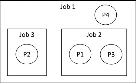
To create this hierarchy, processes should be added to jobs from the root job. Here are a set of steps to create this hierarchy:
1. Add process P1 to job 1.
2. Add process P1 to job 2. This creates the first nesting.
3. Add process P2 to job 1.
4. Add process P2 to job 3. This creates the second nesting.
5. Add process P3 to job 2.
6. Add process P4 to job 1.
EXPERIMENT: Viewing the job object
1. From the command prompt, use the runas command to create a process running the command prompt (Cmd.exe). For example, type runas /user:<domain>\< username> cmd.
2. You’ll be prompted for your password. Enter your password, and a Command Prompt window will appear. The Windows service that executes runas commands creates an unnamed job to contain all processes (so that it can terminate these processes at logoff time).
3. Run Process Explorer, open the Options menu, choose Configure Colors, and check the Jobs entry. Notice that the Cmd.exe process and its child ConHost.exe process are highlighted as part of a job, as shown here:
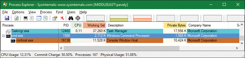
4. Double click the Cmd.exe or ConHost.Exe process to open its properties dialog box. Then click the Job tab to see information about the job this process is part of:
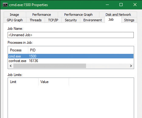
5. From the command prompt, run Notepad.exe.
6. Open Notepad’s process and look at the Job tab. Notepad is running under the same job. This is because cmd.exe does not use the CREATE_BREAKAWAY_FROM_JOB creation flag. In the case of nested jobs, the Job tab shows the processes in the direct job this process belongs to and all processes in child jobs.
7. Run the kernel debugger on the live system and type the !process command to find the notepad.exe and show its basic info:
lkd> !process 0 1 notepad.exe
PROCESS ffffe001eacf2080
SessionId: 1 Cid: 3078 Peb: 7f4113b000 ParentCid: 05dc
DirBase: 4878b3000 ObjectTable: ffffc0015b89fd80 HandleCount: 188.
Image: notepad.exe
...
BasePriority 8
CommitCharge 671
Job ffffe00189aec460
8. Note the Job pointer, which is non-zero. To get a summary of the job, type the !job debugger command:
lkd> !job ffffe00189aec460
Job at ffffe00189aec460
Basic Accounting Information
TotalUserTime: 0x0
TotalKernelTime: 0x0
TotalCycleTime: 0x0
ThisPeriodTotalUserTime: 0x0
ThisPeriodTotalKernelTime: 0x0
TotalPageFaultCount: 0x0
TotalProcesses: 0x3
ActiveProcesses: 0x3
FreezeCount: 0
BackgroundCount: 0
TotalTerminatedProcesses: 0x0
PeakJobMemoryUsed: 0x10db
PeakProcessMemoryUsed: 0xa56
Job Flags
Limit Information (LimitFlags: 0x0)
Limit Information (EffectiveLimitFlags: 0x0)
9. Notice the ActiveProcesses member set to 3 (cmd.exe, conhost.exe, and notepad.exe). You can use flag 2 after the !job command to see a list of the processes that are part of the job:
lkd> !job ffffe00189aec460 2
...
Processes assigned to this job:
PROCESS ffff8188d84dd780
SessionId: 1 Cid: 5720 Peb: 43bedb6000 ParentCid: 13cc
DirBase: 707466000 ObjectTable: ffffbe0dc4e3a040 HandleCount:
<Data Not Accessible>
Image: cmd.exe
PROCESS ffff8188ea077540
SessionId: 1 Cid: 30ec Peb: dd7f17c000 ParentCid: 5720
DirBase: 75a183000 ObjectTable: ffffbe0dafb79040 HandleCount:
<Data Not Accessible>
Image: conhost.exe
PROCESS ffffe001eacf2080
SessionId: 1 Cid: 3078 Peb: 7f4113b000 ParentCid: 05dc
DirBase: 4878b3000 ObjectTable: ffffc0015b89fd80 HandleCount: 188.
Image: notepad.exe
10. You can also use the dt command to display the job object and see the additional fields shown about the job, such as its member level and its relations to other jobs in case of nesting (parent job, siblings, and root job):
lkd> dt nt!_ejob ffffe00189aec460
+0x000 Event : _KEVENT
+0x018 JobLinks : _LIST_ENTRY [ 0xffffe001'8d93e548 -
0xffffe001'df30f8d8 ]
+0x028 ProcessListHead : _LIST_ENTRY [ 0xffffe001'8c4924f0 -
0xffffe001'eacf24f0 ]
+0x038 JobLock : _ERESOURCE
+0x0a0 TotalUserTime : _LARGE_INTEGER 0x0
+0x0a8 TotalKernelTime : _LARGE_INTEGER 0x2625a
+0x0b0 TotalCycleTime : _LARGE_INTEGER 0xc9e03d
...
+0x0d4 TotalProcesses : 4
+0x0d8 ActiveProcesses : 3
+0x0dc TotalTerminatedProcesses : 0
...
+0x428 ParentJob : (null)
+0x430 RootJob : 0xffffe001'89aec460 _EJOB
...
+0x518 EnergyValues : 0xffffe001'89aec988 _PROCESS_ENERGY_VALUES
+0x520 SharedCommitCharge : 0x5e8
Windows containers (server silos)
The rise of cheap, ubiquitous cloud computing has led to another major Internet revolution, in which building online services and/or back-end servers for mobile applications is as easy as clicking a button on one of the many cloud providers. But as competition among cloud providers has increased, and as the need to migrate from one to another, or even from a cloud provider to a datacenter, or from a datacenter to a high-end personal server, has grown, it has become increasingly important to have portable back ends, which can be deployed and moved around as needed without the costs associated with running them in a virtual machine.
It is to satisfy this need that technologies such as Docker were created. These technologies essentially allow the deployment of an “application in a box” from one Linux distribution to another without worrying about the complicated deployment of a local installation or the resource consumption of a virtual machine. Originally a Linux-only technology, Microsoft has helped bring Docker to Windows 10 as part of the Anniversary Update. It can work in two modes:
![]() By deploying an application in a heavyweight, but fully isolated, Hyper-V container, which is supported on both client and server scenarios
By deploying an application in a heavyweight, but fully isolated, Hyper-V container, which is supported on both client and server scenarios
![]() By deploying an application in a lightweight, OS-isolated, server silo container, which is currently supported only in server scenarios due to licensing reasons
By deploying an application in a lightweight, OS-isolated, server silo container, which is currently supported only in server scenarios due to licensing reasons
This latter technology, which we will investigate in this section, has resulted in deep changes in the operating system to support this capability. Note that, as mentioned, the ability for client systems to create server silo containers exists, but is currently disabled. Unlike a Hyper-V container, which leverages a true virtualized environment, a server silo container provides a second “instance” of all user-mode components while running on top of the same kernel and drivers. At the cost of some security, this provides a much more lightweight container environment.
Job objects and silos
The ability to create a silo is associated with a number of undocumented subclasses as part of the SetJobObjectInformation API. In other words, a silo is essentially a super-job, with additional rules and capabilities beyond those we’ve seen so far. In fact, a job object can be used for the isolation and resource management capabilities we’ve looked at as well as used to create a silo. Such jobs are called hybrid jobs by the system.
In practice, job objects can actually host two types of silos: application silos (which are currently used to implement the Desktop Bridge are not covered in this section, and are left for Chapter 9 in Part 2) and server silos, which are the ones used for Docker container support.
Silo isolation
The first element that defines a server silo is the existence of a custom object manager root directory object (\). (The object manager is discussed in Chapter 8 in Part 2.) Even though we have not yet learned about this mechanism, suffice it to say that all application-visible named objects (such as files, registry keys, events, mutexes, RPC ports, and more) are hosted in a root namespace, which allows applications to create, locate, and share these objects among themselves.
The ability for a server silo to have its own root means that all access to any named object can be controlled. This is done in one of three ways:
![]() By creating a new copy of an existing object to provide an alternate access to it from within the silo
By creating a new copy of an existing object to provide an alternate access to it from within the silo
![]() By creating a symbolic link to an existing object to provide direct access to it
By creating a symbolic link to an existing object to provide direct access to it
![]() By creating a brand-new object that only exists within the silo, such as the ones a containerized application would use
By creating a brand-new object that only exists within the silo, such as the ones a containerized application would use
This initial ability is then combined with the Virtual Machine Compute (Vmcompute) service (used by Docker), which interacts with additional components to provide a full isolation layer:
![]() A base Windows image (WIM) file called base OS This provides a separate copy of the operating system. At this time, Microsoft provides a Server Core image as well as a Nano Server image.
A base Windows image (WIM) file called base OS This provides a separate copy of the operating system. At this time, Microsoft provides a Server Core image as well as a Nano Server image.
![]() The Ntdll.dll library of the host OS This overrides the one in the base OS image. This is due to the fact that, as mentioned, server silos leverage the same host kernel and drivers, and because Ntdll.dll handles system calls, it is the one user-mode component that must be reused from the host OS.
The Ntdll.dll library of the host OS This overrides the one in the base OS image. This is due to the fact that, as mentioned, server silos leverage the same host kernel and drivers, and because Ntdll.dll handles system calls, it is the one user-mode component that must be reused from the host OS.
![]() A sandbox virtual file system provided by the Wcifs.sys filter driver This allows temporary changes to be made to the file system by the container without affecting the underlying NTFS drive, and which can be wiped once the container is shut down.
A sandbox virtual file system provided by the Wcifs.sys filter driver This allows temporary changes to be made to the file system by the container without affecting the underlying NTFS drive, and which can be wiped once the container is shut down.
![]() A sandbox virtual registry provided by the VReg kernel component This allows for the provision of a temporary set of registry hives (as well as another layer of namespace isolation, as the object manager root namespace only isolates the root of the registry, not the registry hives themselves).
A sandbox virtual registry provided by the VReg kernel component This allows for the provision of a temporary set of registry hives (as well as another layer of namespace isolation, as the object manager root namespace only isolates the root of the registry, not the registry hives themselves).
![]() The Session Manager (Smss.exe) This is now used to create additional service sessions or console sessions, which is a new capability required by the container support. This extends Smss to handle not only additional user sessions, but also sessions needed for each container launched.
The Session Manager (Smss.exe) This is now used to create additional service sessions or console sessions, which is a new capability required by the container support. This extends Smss to handle not only additional user sessions, but also sessions needed for each container launched.
The architecture of such containers with the preceding components is shown in Figure 3-16.
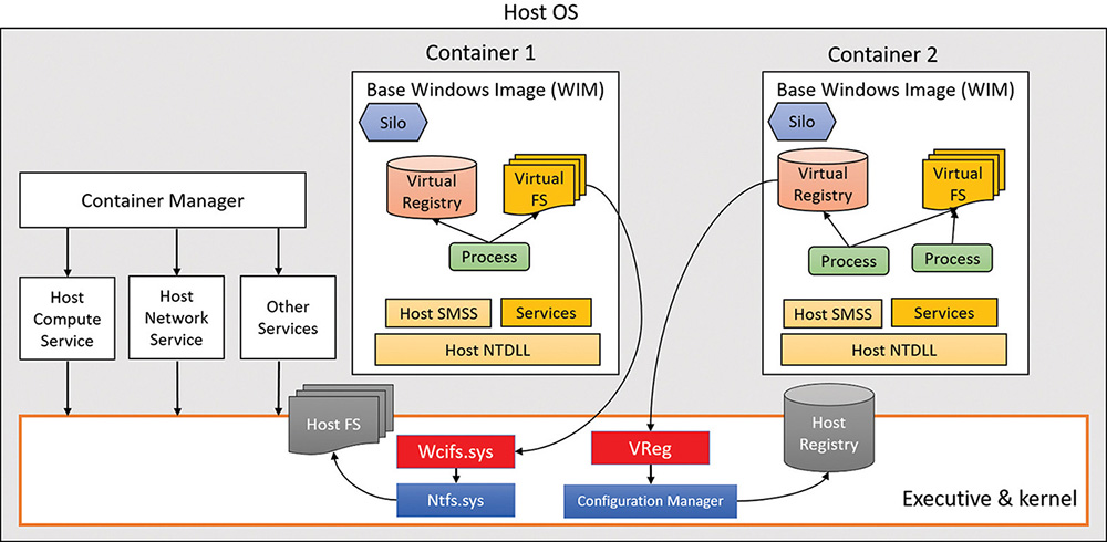
Silo isolation boundaries
The aforementioned components provide the user-mode isolation environment. However, as the host Ntdll.dll component is used, which talks to the host kernel and drivers, it is important to create additional isolation boundaries, which the kernel provides to differentiate one silo from another. As such, each server silo will contain its own isolated:
![]() Micro shared user data (
Micro shared user data (SILO_USER_SHARED_DATA in the symbols) This contains the custom system path, session ID, foreground PID, and product type/suite. These are elements of the original KUSER_SHARED_DATA that cannot come from the host, as they reference information relevant to the host OS image instead of the base OS image, which must be used instead. Various components and APIs were modified to read the silo shared data instead of the user shared data when they look up such data. Note that the original KUSER_SHARED_DATA remains at its usual address with its original view of the host details, so this is one way that host state “leaks” inside container state.
![]() Object directory root namespace This has its own \SystemRoot symlink, \Device directory (which is how all user-mode components access device drivers indirectly), device map and DOS device mappings (which is how user-mode applications access network mapped drivers, for example), \Sessions directory, and more.
Object directory root namespace This has its own \SystemRoot symlink, \Device directory (which is how all user-mode components access device drivers indirectly), device map and DOS device mappings (which is how user-mode applications access network mapped drivers, for example), \Sessions directory, and more.
![]() API Set mapping This is based on the API Set schema of the base OS WIM, and not the one stored on the host OS file system. As you’ve seen, the loader uses API Set mappings to determine which DLL, if any, implements a certain function. This can be different from one SKU to another, and applications must see the base OS SKU, not the host’s.
API Set mapping This is based on the API Set schema of the base OS WIM, and not the one stored on the host OS file system. As you’ve seen, the loader uses API Set mappings to determine which DLL, if any, implements a certain function. This can be different from one SKU to another, and applications must see the base OS SKU, not the host’s.
![]() Logon session This is associated with the
Logon session This is associated with the SYSTEM and Anonymous local unique ID (LUID), plus the LUID of a virtual service account describing the user in the silo. This essentially represents the token of the services and application that will be running inside the container service session created by Smss. For more information on LUIDs and logon sessions, see Chapter 7.
![]() ETW tracing and logger contexts These are for isolating ETW operations to the silo and not exposing or leaking states between the containers and/or the host OS itself. (See Chapter 9 in Part 2 for more on ETW.)
ETW tracing and logger contexts These are for isolating ETW operations to the silo and not exposing or leaking states between the containers and/or the host OS itself. (See Chapter 9 in Part 2 for more on ETW.)
Silo contexts
While these are the isolation boundaries provided by the core host OS kernel itself, other components inside the kernel, as well as drivers (including third party), can add contextual data to silos by using the PsCreateSiloContext API to set custom data associated with a silo or by associating an existing object with a silo. Each such silo context will utilize a silo slot index that will be inserted in all running, and future, server silos, storing a pointer to the context. The system provides 32 built-in system-wide storage slot indexes, plus 256 expansion slots, providing lots of extensibility options.
As each server silo is created, it receives its own silo-local storage (SLS) array, much like a thread has thread-local storage (TLS). Within this array, the different entries will correspond to slot indices that have been allocated to store silo contexts. Each silo will have a different pointer at the same slot index, but will always store the same context at that index. (For example, driver “Foo” will own index 5 in all silos, and can use it to store a different pointer/context in each silo.) In some cases, built-in kernel components, such as the object manager, security reference monitor (SRM), and Configuration Manager use some of these slots, while other slots are used by inbox drivers (such as the Ancillary Function Driver for Winsock, Afd.sys).
Just like when dealing with the server silo shared user data, various components and APIs have been updated to access data by getting it from the relevant silo context instead of what used to be a global kernel variable. As an example, because each container will now host its own Lsass.exe process, and since the kernel’s SRM needs to own a handle to the Lsass.exe process (see Chapter 7 for more information on Lsass and the SRM), this can no longer be a singleton stored in a global variable. As such, the handle is now accessed by the SRM through querying the silo context of the active server silo, and getting the variable from the data structure that is returned.
This leads to an interesting question: What happens with the Lsass.exe that is running on the host OS itself? How will the SRM access the handle, as there’s no server silo for this set of processes and session (that is, session 0 itself)? To solve this conundrum, the kernel now implements a root host silo. In other words, the host itself is presumed to be part of a silo as well! This isn’t a silo in the true sense of the word, but rather a clever trick to make querying silo contexts for the current silo work, even when there is no current silo. This is implemented by storing a global kernel variable called PspHostSilo-Globals, which has its own Slot Local Storage Array, as well as other silo contexts used by built-in kernel components. When various silo APIs are called with a NULL pointer, this "NULL" is instead treated as “no silo—i.e., use the host silo.”
Silo monitors
If kernel drivers have the capability to add their own silo contexts, how do they first know what silos are executing, and what new silos are created as containers are launched? The answer lies in the silo monitor facility, which provides a set of APIs to receive notifications whenever a server silo is created and/or terminated (PsRegisterSiloMonitor, PsStartSiloMonitor, PsUnregisterSiloMonitor), as well as notifications for any already-existing silos. Then, each silo monitor can retrieve its own slot index by calling PsGetSiloMonitorContextSlot, which it can then use with the PsInsertSiloContext, PsReplaceSiloContext, and PsRemoveSiloContext functions as needed. Additional slots can be allocated with PsAllocSiloContextSlot, but this would be needed only if a component would wish to store two contexts for some reason. Additionally, drivers can also use the PsInsertPermanentSiloContext or PsMakeSiloContextPermanent APIs to use “permanent” silo contexts, which are not reference counted and are not tied to the lifetime of the server silo or the number of silo context getters. Once inserted, such silo contexts can be retrieved with PsGetSiloContext and/or PsGetPermanentSiloContext.
Creation of a server silo
When a server silo is created, a job object is first used, because as mentioned, silos are a feature of job objects. This is done through the standard CreateJobObject API, which was modified as part of the Anniversary Update to now have an associated job ID, or JID. The JID comes from the same pool of numbers as the process and thread ID (PID and TID), which is the client ID (CID) table. As such, a JID is unique among not only other jobs, but also other processes and threads. Additionally, a container GUID is automatically created.
Next, the SetInformationJobObject API is used, with the create silo information class. This results in the Silo flag being set inside of the EJOB executive object that represents the job, as well as the allocation of the SLS slot array we saw earlier in the Storage member of EJOB. At this point, we have an application silo.
After this, the root object directory namespace is created with another information class and call to SetInformationJobObject. This new class requires the trusted computing base (TCB) privilege. As silos are normally created only by the Vmcompute service, this is to ensure that virtual object namespaces are not used maliciously to confuse applications and potentially break them. When this namespace is created, the object manager creates or opens a new Silos directory under the real host root (\) and appends the JID to create a new virtual root (e.g., \Silos\148\). It then creates the Kernel-Objects, ObjectTypes, GLOBALROOT, and DosDevices objects. The root is then stored as a silo context with whatever slot index is in PsObjectDirectorySiloContextSlot, which was allocated by the object manager at boot.
The next step is to convert this silo into a server silo, which is done with yet another call to Set-InformationJobObject and another information class. The PspConvertSiloToServerSilo function in the kernel now runs, which initializes the ESERVERSILO_GLOBALS structure we saw earlier as part of the experiment dumping the PspHostSiloGlobals with the !silo command. This initializes the silo shared user data, API Set mapping, SystemRoot, and the various silo contexts, such as the one used by the SRM to identify the Lsass.exe process. While conversion is in progress, silo monitors that have registered and started their callbacks will now receive a notification, such that they can add their own silo context data.
The final step, then, is to “boot up” the server silo by initializing a new service session for it. You can think of this as session 0, but for the server silo. This is done through an ALPC message sent to Smss SmApiPort, which contains a handle to the job object created by Vmcompute, which has now become a server silo job object. Just like when creating a real user session, Smss will clone a copy of itself, except this time, the clone will be associated with the job object at creation time. This will attach this new Smss copy to all the containerized elements of the server silo. Smss will believe this is session 0, and will perform its usual duties, such as launching Csrss.exe, Wininit.exe, Lsass.exe, etc. The “boot-up” process will continue as normal, with Wininit.exe then launching the Service Control Manager (Services.exe), which will then launch all the automatic start services, and so on. New applications can now execute in the server silo, which will run with a logon session associated with a virtual service account LUID, as described earlier.
Ancillary functionality
You may have noticed that the short description we’ve seen so far would obviously not result in this “boot” process actually succeeding. For example, as part of its initialization, it will want to create a named pipe called ntsvcs, which will require communicating with \Device\NamedPipe, or as Services.exe sees it, \Silos\JID\Device\NamedPipe. But no such device object exists!
As such, in order for device driver access to function, drivers must be enlightened and register their own silo monitors, which will then use the notifications to create their own per-silo device objects. The kernel provides an API, PsAttachSiloToCurrentThread (and matching PsDetachSiloFromCurrentThread), which temporarily sets the Silo field of the ETHREAD object to the passed-in job object. This will cause all access, such as that to the object manager, to be treated as if it were coming from the silo. The named pipe driver, for example, can use this functionality to then create a NamedPipe object under the \Device namespace, which will now be part of \Silos\JID\.
Another question is this: If applications launch in essentially a “service” session, how can they be interactive and process input and output? First, it is important to note that there is no GUI possible or permitted when launching under a Windows container, and attempting to use Remote Desktop (RDP) to access a container will also be impossible. As such, only command-line applications can execute. But even such applications normally need an “interactive” session. So how can those function? The secret lies in a special host process, CExecSvc.exe, which implements the container execution service. This service uses a named pipe to communicate with the Docker and Vmcompute services on the host, and is used to launch the actual containerized applications in the session. It is also used to emulate the console functionality that is normally provided by Conhost.exe, piping the input and output through the named pipe to the actual command prompt (or PowerShell) window that was used in the first place to execute the docker command on the host. This service is also used when using commands such as docker cp to transfer files from or to the container.
Container template
Even if we take into account all the device objects that can be created by drivers as silos are created, there are still countless other objects, created by the kernel as well as other components, with which services running in session 0 are expected to communicate, and vice-versa. In user mode, there is no silo monitor system that would somehow allow components to support this need, and forcing every driver to always create a specialized device object to represent each silo wouldn’t make sense.
If a silo wants to play music on the sound card, it shouldn’t have to use a separate device object to represent the exact same sound card as every other silo would access, as well as the host itself. This would only be needed if, say, per-silo object sound isolation was required. Another example is AFD. Although it does use a silo monitor, this is to identify which user-mode service hosts the DNS client that it needs to talk to service kernel-mode DNS requests, which will be per-silo, and not to create separate \Silos\JID\Device\Afd objects, as there is a single network/Winsock stack in the system.
Beyond drivers and objects, the registry also contains various pieces of global information that must be visible and exist across all silos, which the VReg component can then provide sandboxing around.
To support all these needs, the silo namespace, registry, and file system are defined by a specialized container template file, which is located in %SystemRoot%\System32\Containers\wsc.def by default, once the Windows Containers feature is enabled in the Add/Remove Windows Features dialog box. This file describes the object manager and registry namespace and rules surrounding it, allowing the definition of symbolic links as needed to the true objects on the host. It also describes which job object, volume mount points, and network isolation policies should be used. In theory, future uses of silo objects in the Windows operating system could allow different template files to be used to provide other kinds of containerized environments. The following is an excerpt from wsc.def on a system for which containers are enabled:
<!-- This is a silo definition file for cmdserver.exe -->
<container>
<namespace>
<ob shadow="false">
<symlink name="FileSystem" path="\FileSystem" scope="Global" />
<symlink name="PdcPort" path="\PdcPort" scope="Global" />
<symlink name="SeRmCommandPort" path="\SeRmCommandPort" scope="Global" />
<symlink name="Registry" path="\Registry" scope="Global" />
<symlink name="Driver" path="\Driver" scope="Global" />
<objdir name="BaseNamedObjects" clonesd="\BaseNamedObjects" shadow="false"/>
<objdir name="GLOBAL??" clonesd="\GLOBAL??" shadow="false">
<!-- Needed to map directories from the host -->
<symlink name="ContainerMappedDirectories" path="\
ContainerMappedDirectories" scope="Local" />
<!-- Valid links to \Device -->
<symlink name="WMIDataDevice" path="\Device\WMIDataDevice" scope="Local"
/>
<symlink name="UNC" path="\Device\Mup" scope="Local" />
...
</objdir>
<objdir name="Device" clonesd="\Device" shadow="false">
<symlink name="Afd" path="\Device\Afd" scope="Global" />
<symlink name="ahcache" path="\Device\ahcache" scope="Global" />
<symlink name="CNG" path="\Device\CNG" scope="Global" />
<symlink name="ConDrv" path="\Device\ConDrv" scope="Global" />
...
<registry>
<load
key="$SiloHivesRoot$\Silo$TopLayerName$Software_Base"
path="$TopLayerPath$\Hives\Software_Base"
ReadOnly="true"
/>
...
<mkkey
name="ControlSet001"
clonesd="\REGISTRY\Machine\SYSTEM\ControlSet001"
/>
<mkkey
name="ControlSet001\Control"
clonesd="\REGISTRY\Machine\SYSTEM\ControlSet001\Control"
/>
Conclusion
This chapter examined the structure of processes, including the way processes are created and destroyed. We’ve seen how jobs can be used to manage a group of processes as a unit and how server silos can be used to usher in a new era of container support to Windows Server versions. The next chapter delves into threads—their structure and operation, how they’re scheduled for execution, and the various ways they can be manipulated and used.


Comments
Post a Comment